Matter Core
Chapter 1. Introduction
Chapter 01 — Introduction Document
Chapter 02 — Architecture Document
Chapter 03 — Cryptographic Primitives Document
Chapter 04 — Secure Channel Document
Chapter 05 — Commissioning Document
Chapter 06 — Device Attestation Document
Chapter 07 — Data Model Document
Chapter 08 — Interaction Model Document
Chapter 09 — System Model Document
Chapter 10 — Interaction Encoding Document
Chapter 11 — Device Management Document
Chapter 12 — Multiple Fabrics Document
Chapter 13 — Security Requirements Document
Chapter 2. Architecture
2.1. Overview
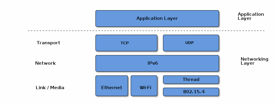
Figure 1. Application and Network Stack
2.2. Layered Architecture
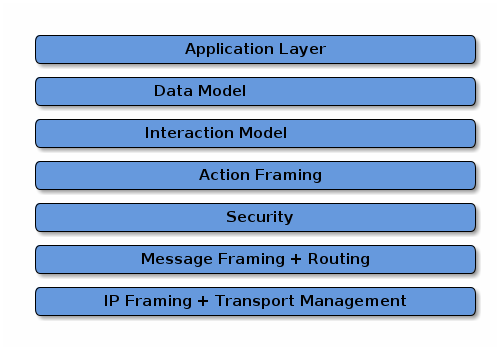
Figure 2. Layered Architecture
The
Application layercorresponds to the high order business logic of a device. For example, an application that is focused on lighting might contain logic to handle turning on/off a light bulb, as well as its color characteristics.The
Data Model layercorresponds to the data and verb elements that help support the functionality of the application. The Application operates on these data structures when there is intent to interact with the device.The
Interaction Model layerdefines a set of interactions that can be performed between a client and server device. For example, reading or writing attributes on a server device would correspond to application behavior on the device. These interactions operate on the elements defined at the data model layer.The
Action Framing layer: Once an action is constructed using the Interaction Model, it is serialized into a prescribed packed binary format to encode for network transmission.The
Security Layer: the message is encrypted and appended with a message authentication code. These actions ensure the data remain confidential and authentic between sender and receiver of the message.The
Message Layerconstructs the payload format with required and optional header fields, which specify properties of the message as well logical routing information. After the final payload has been constructed by the Message Layer, it is sent to the underlying transport protocol (TCP or MRP) for IP management of the data.
2.3. Network Topology
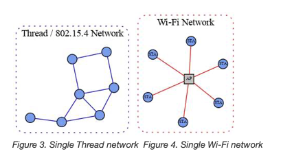
Single Network: Figure 3. Single Thread network; Figure 4. Single Wi-Fi network
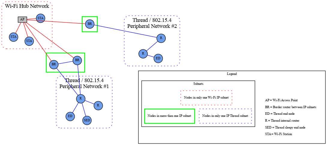
Figure 5. Star network topology
2.4. Scoped names
A Fabric is a collection of Matter devices sharing a trusted root.
Fabrics are uniquely identified by the tuple of their root CA’s public key and a Fabric ID.
A Matter device may be a member of multiple fabrics and thus have multiple associated node IDs.
2.5. Identifiers
Fabric IDis a 64-bit numberFabric ID0 is reserved across all fabric root public key scopes.Vendor IDis a 16-bit numberProduct IDis a 16-bit numberGroup IDis a 16-bit numberNode IDis a 64-bit number
Table 2. Group ID Allocations
Range |
Type |
|---|---|
0xFF00 - 0xFFFF |
Universal Group ID range reserved for static multicast and anycast identifiers |
0x0001 - 0xFEFF |
Application Group ID, assigned by fabric Administrator |
0x0000 |
Null or unspecified Group ID |
Table 3. Universal Group ID Allocations
Range |
Type |
|---|---|
0xFFFF |
All Nodes |
0xFFFE |
All non-sleepy Nodes |
0xFFFD |
All Proxies |
0xFF00-0xFFFC |
Reserved for future use |
Table 4. Node Identifier Allocations
Range |
Type |
|---|---|
0xFFFF_FFFF_FFFF_xxxx |
Group Node ID |
0xFFFF_FFFF_0000_0000 to 0xFFFF_FFFF_FFFE_FFFF |
Reserved for future use |
0xFFFF_FFFE_xxxx_xxxx |
Temporary Local Node ID |
0xFFFF_FFFD_xxxx_xxxx |
CASE Authenticated Tag |
0xFFFF_FFFC_xxxx_xxxx to 0xFFFF_FFFC_FFFF_FFFF |
Reserved for future use |
0xFFFF_FFFB_xxxx_xxxx |
PAKE key identifiers |
0xFFFF_FFF0_0000_0000 to 0xFFFF_FFFA_FFFF_FFFF |
Reserved for future use |
0x0000_0000_0000_0001 to 0xFFFF_FFEF_FFFF_FFFF |
Operational Node ID |
0x0000_0000_0000_0000 |
Unspecified Node ID |
2.5.6. IPv6 Addressing
IPv6 Unicast Address includes a
global unicast address (GUA), alink-local address (LLA), or aunique local address (ULA).IPv6 Multicast Port Number is
5540.IPv6 Multicast Address:
1. The first 12 bits are defined by [RFC 3306] and are `0xFF3`
2. The next 4 bits are "scop" (scope) and set based [RFC 7346] to:Site-Local (`0x5`)
    spans all networks in the Fabric, including Thread, Ethernet, and Wi-Fi.
3. The next 8 bits are reserved (`0x00`).
4. The next 8 bits are "plen", set to `0x40` to indicate a 64-bit long network prefix field
5. The next 8 bits are a locally assigned ULA prefix per [RFC 4193 3.1], set to `0xFD`
6. The next 64 bits are the `Fabric ID` for the network in big-endian order
7. 0x00
8. The next 16-bits are the `Group Identifier` for the group in big-endian order

示例:
IPv6格式: 128位,分为8组,每组四个十六进制
FF35:0040:FD<Fabric ID>00:<Group ID>
2.6. Device identity
Device Attestation Certificate (DAC)
Operational Node ID and a Node Operational Certificate (NOC) for that Operational Node ID, is issued, during the commissioning process of a device into a Fabric.
2.7. Security
Detailed in
Chapter 3, Cryptographic PrimitivesElliptic curve cryptography, based on the NIST P-256 curve (secp256r1) serves as the foundation for public key cryptography and digital signatures.
Commonly available AES modes of operation have been selected to provide shared key cryptographic operations.
In scenarios involving an out-of-band passcode-based authentication, Matter uses SPAKE2+, an efficient augmented PAKE algorithm.
2.8. Device Commissioning
Detailed in
Chapter 5, Commissioning
Device discovery
Security setup with PASE
Device attestation verification
Information configuration: Commissioner provides Commissionee with information such as regulatory domain, UTC time, Operational Certificate and network interfaces configuration.
Join network
Security setup with CASE
Commissioning complete message exchange
2.9. Sleepy End Device (SED)
Idle mode, or slow-polling, sets the maximum time a SED will sleep before polling.
Active mode sets the SED into a fast-polling interval for maximum responsiveness when the Node is engaged in ongoing communication, such as an active Exchange.
A Node determines whether it is in Active or Idle mode based on whether it has any outstanding Exchanges in the Message Layer. While there are Exchanges active, a node will remain in Active mode and poll at the fast-polling interval if it is a SED. Once all Exchanges are closed, a node SHOULD transition into Idle mode and poll at the slow-polling interval if it is a SED and the node has no other outstanding reasons for staying awake.
2.10. Data Model Root
Endpoint 0 (zero) SHALL be the root node endpoint.
Endpoint 0 (zero) SHALL support the Root Node device type.
2.11. Stack Limits
2.11.1. System Model Limits
2.11.1.1. Access Control Limits:
 A node SHALL guarantee that there are at least three Access Control Entries
    available for every fabric supported by the node

Device types MAY impose additional constraints
    on the number of ACL entries that need to be supported.
2.11.1.2. Group Limits:
A node SHALL support at least one group key per fabric for managing the IPK.
If the node implements one or more device types with support for the Groups cluster,
    the node SHALL additionally support the maximum number of the required groups
        as specified by all of these implemented device types.
A node SHALL support one IPv6 multicast group membership for every operational group it supports.
Support for GroupKeyMulticastPolicy field in GroupKeySetStruct is provisional.
2.11.2. Interaction Model Limits
2.11.2.1. Read Interaction Limits
2.11.2.2. Subscribe Interaction Limits
2.11.2.3. Invoke Interaction Limits
2.12. List of Provisional Items
Support for an Invoke Interaction with multiple paths or wildcard paths is provisional.
The EventList global attribute is provisional.
The Proxy Architecture, the Proxy Config and Proxy Discovery clusters are provisional.
The Time Synchronization feature is provisional.
Chapter 3. Cryptographic Primitives
Chapter 4. Secure Channel
4.1. General Description
Unsecured communication is strictly limited to:
• Discovery, which does not use the Matter message format.
• User Directed Commissioning (UDC),
    which uses unsecured messages to initiate the commissioning process.
• Session establishment, which uses unsecured messages to establish a CASE or PASE session.
4.1.1.1. Message Types:
1. control message
2. data message
4.1.1.2. Message Transports:
1. UDP transports each message as a separate datagram.
2. TCP transports each message with a length prepended,
    performing segmentation and reassembly as needed.
3. BTP transports each message over BLE as a separate SDU,
    performing segmentation and reassembly as needed.
4.1.1.3. Message Exchanges:
Message Exchanges Layer
Message Session Layer
Message Encode/Decode
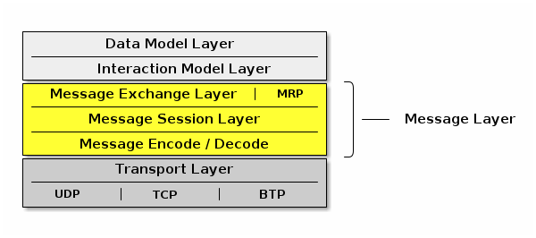
Figure 6. Message Layer Stack
4.2. IPv6 Reachability
a Matter network is composed of (typically one)
infrastructure networkand one or morestub networks.Unlike an infrastructure network, stub networks do not serve as transit networks.
the
infrastructure networkis a bridged Wi-Fi / Ethernet networkthe Thread networks are
stub networks.A stub router connects a
stub networkto aninfrastructure networkand provides IPv6 reachability between the two networks.
4.2.1. Stub Router Behavior
A stub router SHALL implement [draft-lemon-stub-networks]
If there is no routable prefix on a given network, the stub router SHALL provide its own routable prefix.
Thread’s “on-mesh prefix” is equivalent to Wi-Fi / Ethernet’s “on-link prefix”.
4.2.2. Matter Node Behavior
Matter Nodes SHALL configure a link-local IPv6 address.
Nodes SHALL support configuration of at least three routable IPv6 addresses(link-local, Thread, mesh-local addresses).
4.3. Discovery
Service Advertising and Discovery is used within Matter in the following contexts:
• Commissionable Node Discovery
• Operational Discovery
• Commissioner Discovery
• User Directed Commissioning
Matter software advertising the availability of a service SHOULD indicate that announcements and answers for this service need include only IPv6 address records, not IPv4 address records.
A Thread Border Router SHALL implement DNS-SD Discovery Proxy [RFC 8766] to enable clients on the Thread mesh (e.g., other Nodes) to discover services (e.g., Matter Nodes) advertised using Multicast DNS on an adjacent Ethernet or Wi‐Fi link, also without the cost of using multicast on the Thread mesh [draft-lemon-stub-networks].
For short-lived instantaneous queries, these queries can be performed using unicast DNS over UDP to the DNS-SD Discovery Proxy.
For long-lived queries with ongoing change notification, DNS Push Notifications [RFC 8765] with DNS Stateful Operations [RFC 8490] allows clients on the Thread mesh to be notified of changes to the set of discovered services without expensive polling.
4.3.1. Commissionable Node Discovery
For Matter Commissionable Node Discovery in the already-on-network and Soft-AP cases, the DNS-SD instance name SHALL be a dynamic, pseudo-randomly selected, 64-bit temporary unique identifier: DD200C20D25AE5F7.
The target host name SHALL be constructed using one of the available link-layer addresses, such as a 48-bit device MAC address (for Ethernet and Wi‐Fi) or a 64-bit MAC Extended Address (for Thread)
While Section 5.4.2.3, “Announcement Duration” is limited for some forms of device advertisement, a Matter device MAY advertise Matter Commissionable Node Discovery service records for longer periods, possibly permanently. Advertising Commissionable Node Discovery when not in Commissioning Mode is referred to here as Extended Discovery.
Extended Discovery is allowed only for DNS-SD advertisements and not for the other forms of Device Discovery such as BLE Commissioning Discovery and Wi-Fi Temporary Access Point Commissioning Discovery.
4.3.1.3. Commissioning Subtypes:
1. _L<ddd>, where <ddd> provides the full 12-bit discriminator
2. _S<d>, where <d> provides the upper 4 bits of the discriminator
3. _V<dddd>, where <ddddd> provides the 16-bit Vendor ID
4. _T<dd>, where <dd> provides the device type identifier for the device
5. _CM, which represents "currently in Commissioning Mode"

示例:
    _L840
    _S3
    _V1234
    _T10
    _CM
4.3.1.4. TXT Records:
1. discriminator (D)
2. Vendor ID and Product ID (VP)
3. commissioning mode (CM)
4. device type (DT)
5. device name (DN)
6. rotating device identifier (RI)
7. pairing hint (PH)
8. pairing instructions (PI)
Examples are shown using both the
dns-sdcommand-line test tool and theavahicommand-line test tool.
4.3.2. Operational Discovery
For Matter Nodes that have already been commissioned onto a Matter Fabric, run-time dynamic discovery of operational Matter Nodes is used, rather than assuming a fixed unchanging IPv6 address and port for the lifetime of the product.
Operational Instance Name: a Matter Node with Matter compressed fabric identifier 2906-C908-D115-D362 and Matter Node identifier 8FC7-7724-01CD-0696 has Matter operational discovery DNS-SD instance name 2906C908D115D362-8FC7772401CD0696.
Compressed Fabric Identifier: In order to reduce the very large size of a full Fabric Reference which would need to be used as the scoping construct in the instance name, a 64-bit compressed version of the full Fabric Reference SHALL be used.
4.3.3. Commissioner Discovery
A Commissionee MAY initiate the commissioning process by discovering Commissioners on the network
4.3.4. Common TXT Key/Value Pairs
The TXT records provided during Commissionable, Operational and Commissioner discovery MAY contain the following optional key/value pairs which are common to every discovery method:
1. The optional key SII indicates the SLEEPY_IDLE_INTERVAL of the Node
    - Example: SII=5300 to override the initial retry interval value to 5.3 seconds.
2. The optional key SAI indicates the SLEEPY_ACTIVE_INTERVAL of the Node
    - Example: SAI=1250 to override the active retry interval value to 1.25 seconds.
3. The optional key T indicates whether the Node supports TCP
    - Example: T=1 to announce TCP is supported by the advertising Node.
4.4. Message Frame Format
The Matter message format provides flexible support for various communication paradigms:
1. unicast secure sessions
2. multicast group messaging
3. session establishment itself
Matter Message format definition:
1. Message Header
    2 bytes     [ Message Length ]
    1 byte      Message Flags
    2 bytes     Session ID
    1 byte      Security Flags
    4 bytes     Message Counter
    0/8 bytes   [ Source Node ID ]
    0/2/8 bytes [ Destination Node ID ]
    variable    [ Message Extensions . . . ]
2. Message Payload
    variable    [ Message Payload . . . ] (encrypted)
3. Message Footer
    variable    [ Message Integrity Check ]
Message Payload of a Matter message SHALL contain a Protocol Message with format as follows:
1. Protocol Header
    1 byte      Exchange Flags
    1 byte      Protocol Opcode
    2 bytes     Exchange ID
    2 bytes     Protocol ID
    2 bytes     [ Protocol Vendor ID ]
    4 bytes     [ Acknowledged Message Counter ]
    variable    [ Secured Extensions . . . ]
2. Application Payload
    variable    [ Application Payload . . . ]
4.4.1. Message Header Field Descriptions
4.4.1.1. Message Length (16 bits):
not including the size of the Message Length field itself.

This field SHALL only be present
    when the message is being transmitted over a stream-oriented channel such as TCP.
The message length is equal to the payload length of the UDP packet
    when transmitted over UDP
4.4.1.2. Message Flags (8 bits):
格式:
+---+---+---+---+---+---+---+---+
| 7 | 6 | 5 | 4 | 3 | 2 | 1 | 0 |
+===============+===+===+===+===+
|    Version    | - | S |  DSIZ |
+---------------+---+---+---+---+

说明:
Version (4 bits, positions 4-7):
    • 0 — Matter Message Format version 1.0
    • 1-15 — Reserved for future use
S Flag (1 bit)
    SHALL be set if and only if the Source Node ID field is present.
DSIZ Field (2 bits)
    • 0 — Destination Node ID field is not present
    • 1 — Destination Node ID field is present as a 64-bit Node ID
    • 2 — Destination Node ID field is present as a 16-bit Group ID
    • 3 — Reserved for future use
4.4.1.3. Session ID (16 bits):
An unsigned integer value identifying the session associated with this message.
The session identifies the particular key used to encrypt a message
    out of the set of available keys (either session or group),
    and the particular encryption/message integrity algorithm to use for the message.
4.4.1.4. Security Flags (8 bits):
格式:
+---+---+---+---+---+---+---+---+
| 7 | 6 | 5 | 4 | 3 | 2 | 1 | 0 |
+===+===+===+===========+===+===+
| P | C | MX|  Reserved |  Type |
+---------------+---+---+---+---+

说明:
P Flag (1 bit, position 7):
    Privacy (P) flag
    when set, SHALL identify that the message is encoded with privacy enhancements
C Flag (1 bit, position 6):
    Control message (C) flag
    when set, SHALL identify that the message is a control message
MX Flag (1 bit, position 5):
    Message Extensions (MX) flag
     when set, SHALL indicate that the Message Extensions portion of the message is present
Session Type (2 bit, position 0-1):
    • 0 — Unicast Session
    • 1 — Group Session
    • 2-3 — Reserved for future use
4.4.1.5. Message Counter (32 bits):
uniquely identifying the message from the perspective of the sending node.
The message counter is generated based on the Session Type
    and increases monotonically for each unique message generated.
When messages are retransmitted the counter remains the same
4.4.1.6. Source Node ID (64 bits):
unique identifier of the source node
The Source Node ID field SHALL only be present in a message
    when the S Flag in the Message Flags field is set to 1.
4.4.1.7. Destination Node ID:
unique Node Identifier of the destination Node or group
    to which the message is being sent.
The size and encoding of the Destination Node ID field
    depends on the value of the DSIZ field.
4.4.1.8. Message Extensions (variable):
The Message Extensions block SHALL be present only if the MX Flag is set to 1

说明:
2 bytes:    Message Extensions Payload Length, in bytes
variable:   [ Message Extensions Payload ]
4.4.3. Protocol Header Field Descriptions
4.4.3.1. Exchange Flags (8 bits):
格式:
+---+---+---+---+---+---+---+---+
| 7 | 6 | 5 | 4 | 3 | 2 | 1 | 0 |
+===============+===+===+===+===+
|  Reserved | V | SX| R | A | I |
+---------------+---+---+---+---+

说明:
I Flag (1 bit, position 0):
    Initiator (I) flag
    when set, SHALL indicate that the message was sent by the initiator of the exchange.
A Flag (1 bit, position 1):
    Acknowledgement (A) flag
    when set, SHALL indicate that the message serves as an acknowledgement
        of a previous message received by the current message sender.
R Flag (1 bit, position 2):
    Reliability (R) flag
    when set, SHALL indicate that the message sender wishes to
        receive an acknowledgement for the message.
SX Flag (1 bit, position 3):
    Secured Extensions (SX) flag
    when set, SHALL indicate that
        the Secured Extensions portion of the message is present and has non-zero length.
V Flag (1 bit, position 4):
    Vendor (V) protocol flag
    when set, SHALL indicate whether the Protocol Vendor ID is present.
4.4.3.2. Protocol Opcode (8 bits):
identifying the type of the message.
4.4.3.3. Exchange ID (16 bits):
identifying the exchange to which the message belongs
4.4.3.4. Protocol ID (16 bits):
identifying the protocol in which the Protocol Opcode of the message is defined.

When the Protocol Vendor ID is the ``Matter Standard Vendor ID``:
+-----------------+-----------------------------------------+
| Range           | Type                                    |
+=================+=========================================+
| 0x0000          | PROTOCOL_ID_SECURE_CHANNEL              |
+-----------------+-----------------------------------------+
| 0x0001          | PROTOCOL_ID_INTERACTION_MODEL           |
+-----------------+-----------------------------------------+
| 0x0002          | PROTOCOL_ID_BDX                         |
+-----------------+-----------------------------------------+
| 0x0003          | PROTOCOL_ID_USER_DIRECTED_COMMISSIONING |
+-----------------+-----------------------------------------+
| 0x0004          | PROTOCOL_ID_FOR_TESTING                 |
+-----------------+-----------------------------------------+
| 0x0005 - 0xFFFF | reserved                                |
+-----------------+-----------------------------------------+
4.4.3.5. Protocol Vendor ID (16 bits):
This field SHALL only be present when the V Flag is set;
otherwise the default is 0, corresponding to the Matter Standard Vendor ID.
4.4.3.6. Acknowledged Message Counter (32 bits):
containing the message counter of a previous message
    that is being acknowledged by the current message.

SHALL only be present when the A Flag in the Exchange Flags field is 1.
4.4.3.7. Secured Extensions (variable):
 for providing backwards compatible extensibility.
 SHALL be present only if the SX Flag is set to 1 in the Exchange Flags field.

Secured Extensions block format definition:
+----------+----------------------------------------------+
| Length   | Field                                        |
+==========+==============================================+
| 2 bytes  | Secured Extensions Payload Length, in bytes. |
+----------+----------------------------------------------+
| variable | [ Secured Extensions Payload ]               |
+----------+----------------------------------------------+
4.4.3.8. Application Payload (variable length):
A sequence of zero or more bytes containing the application data conveyed by the message.
4.4.4. Message Size Requirements
Support for IPv6 fragmentation is not mandatory in Matter, and the expected supported MTU is 1280 bytes, the minimum required by IPv6.
Therefore, all messages, including transport headers, SHALL fit within that minimal IPv6 MTU.
This message size limit SHALL apply to the UDP transport.
A message received over UDP that exceeds this message size limit SHALL NOT be processed.
Messages sent over TCP or BTP over BLE transports MAY exceed the message size limit if both nodes are capable of supporting larger message sizes.
4.5. Message Counters
Message counters serve several purposes:
1. Duplicate Message Detection
2. Message Acknowledgement
3. Encryption Nonces
4. Replay Prevention
4.5.1. Message Counter Types
All Nodes implement three global 32-bit counters to vend message counters for certain types of messages:
• Global Unencrypted Message Counter
• Global Group Encrypted Data Message Counter
• Global Group Encrypted Control Message Counter
Nodes implement a separate 32-bit counter for each session as part of secure session state:
• Secure Session Message Counter
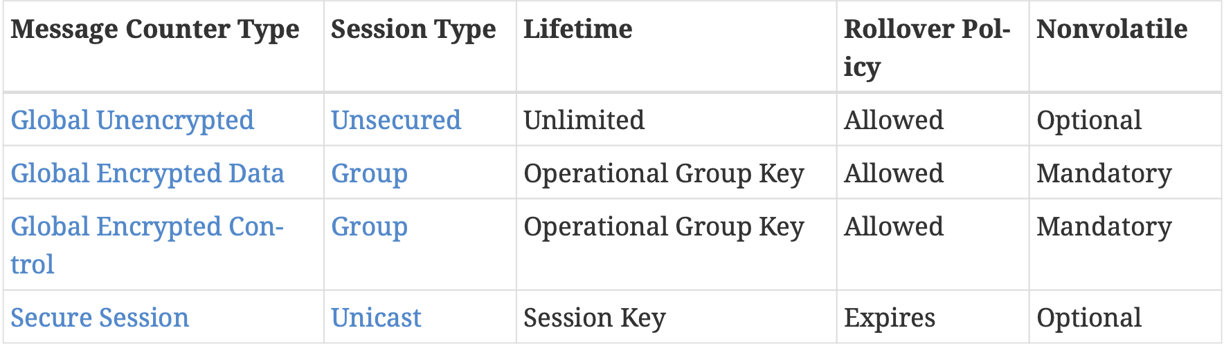
Table 15. Message Counter Type Overview
4.5.1.2. Global Unencrypted Message Counter
Typically, Nodes store the Global Unencrypted Message Counter in RAM. This makes the counter subject to loss whenever the system reboots or otherwise loses its state.
This is permissible because retaining the Global Unencrypted Message Counter is not essential to the confidentiality or integrity of the message.
In the event that the Global Unencrypted Message Counter for a Node is lost, Nodes SHALL randomize the initial value of this counter on startup
4.5.1.3. Global Group Encrypted Message Counters
There are two such counters:
• Global Group Encrypted Data Message Counter
    encode regular data messages encrypted with a group key.

• Global Group Encrypted Control Message Counter
    encode control messages encrypted with a group key.
4.5.2. Secure Session Message Counters
used by the encoding of any encrypted messages using an associated session key.
Each peer in a Secure Unicast Session SHALL maintain its own message counters, with independent counters being used for each unique session used.
The Secure Session Message Counter history window SHALL be maintained for the lifetime of the session, and SHALL be deleted at the same time as the session keys, when the session ends.
4.5.3. Message Counters as Encryption Nonces
As Encryption Nonces makes decrypt more harder
4.5.4. Replay Prevention and Duplicate Message Detection
Message duplication may occur for a number of reasons:
1. out-of-order arrival,
2. network latency,
3. malicious attack,
4. network error.
4.5.5. Counter Processing of Outgoing Messages
Obtain the outgoing message counter of the sending Node
The outgoing message counter from step 1 SHALL be incremented by 1.
Store the incremented outgoing message counter in the OutgoingMessageCounter element associated with the Session Context for the message.
4.5.6. Counter Processing of Incoming Messages
Determine the Message Reception State for the sending peer and get the current max_message_counter.
If the Message Counter is outside the valid message counter window, the message SHALL be marked as a duplicate.
4.6. Message Processing
4.6.1. Message Transmission
4.6.2. Message Reception
4.7. Message Security
4.7.1. Data confidentiality and integrity with data origin authentication parameters
Section 3.6, “Data Confidentiality and Integrity”.
4.7.1.1. Nonce:
数据格式:
    Security Flags(4bit) Message Counter(4*4bit) Source Node ID(8*4bit)
    little-endian byte order

• If the message is of Secure Unicast Session Type:
    For a CASE session,
        Source Node ID=determined via the Secure Session Context associated with the Session Identifier.
    For a PASE session,
        Source Node ID=Unspecified Node ID.
• If the message is of Group Session Type:
    The S Flag of the message SHALL be 1
        and the Nonce Source Node ID SHALL be the SourceNode ID of the message.
    If the S Flag of the message is 0 the message SHALL be dropped.
4.7.2. Security Processing of Outgoing Messages
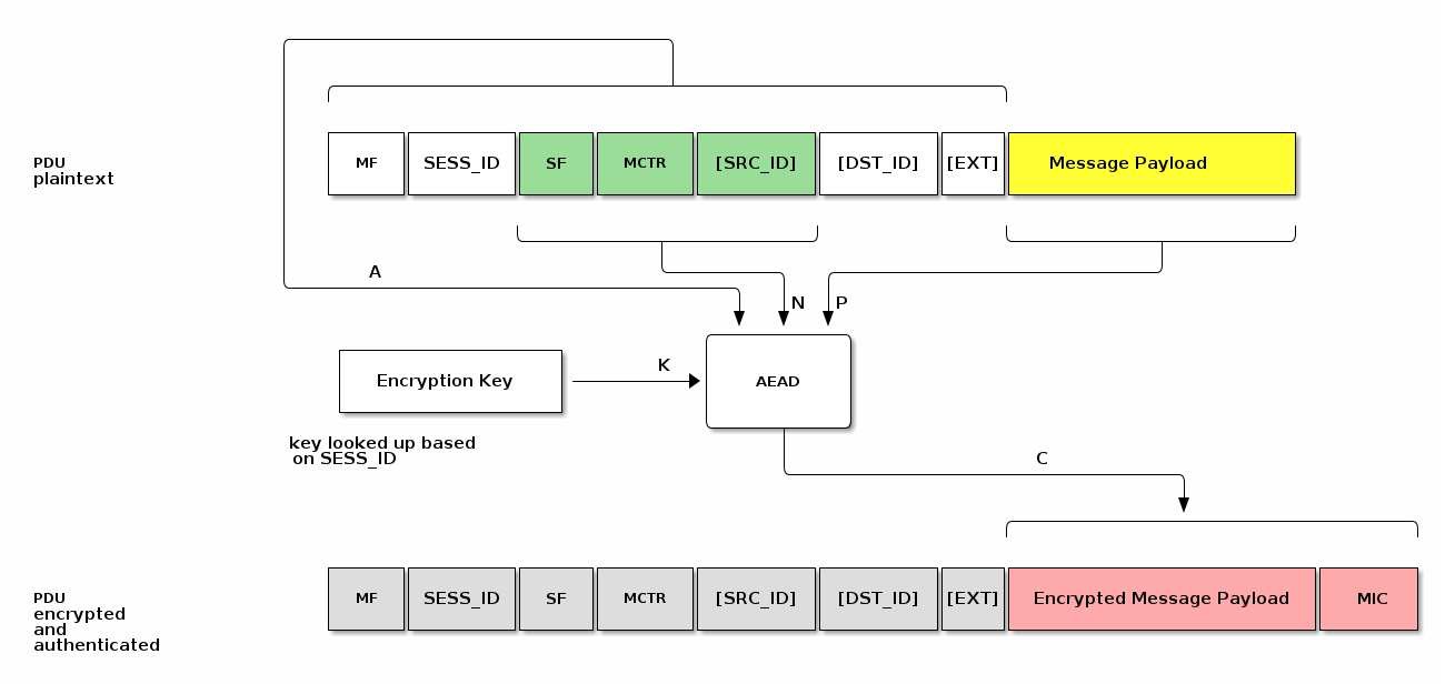
Figure 8. Matter Message Encryption
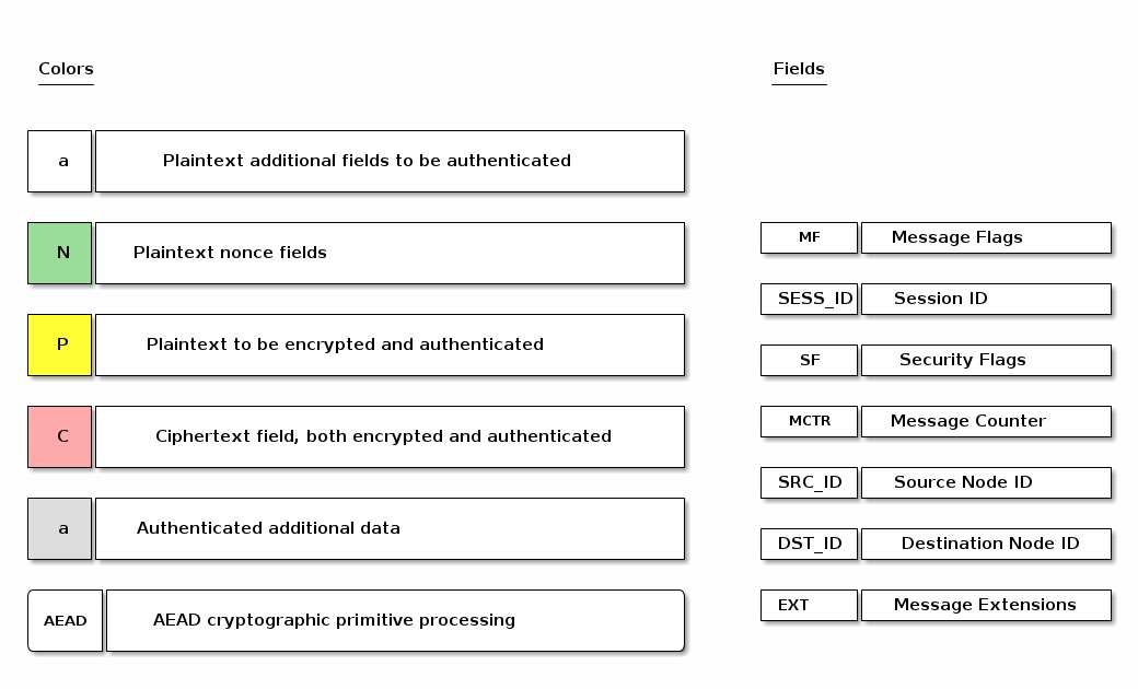
Figure 9. Matter Message Encryption Legend
4.7.3. Security Processing of Incoming Messages
4.8. Message Privacy
rely on the cryptographic primitives in Section 3.7, “Message privacy”.
4.8.1. Privacy Key
Privacy Key is derived as follows:
PrivacyKey =
    Crypto_KDF
    (
       InputKey = EncryptionKey,
       Salt = [],
       Info = "PrivacyKey",
       Length = CRYPTO_SYMMETRIC_KEY_LENGTH_BITS
    )
4.8.2. Privacy Nonce
The Privacy Nonce SHALL be the CRYPTO_AEAD_NONCE_LENGTH_BYTES-octet string constructed as the 16-bit Session ID (in big-endian format) concatenated with the lower 11 (i.e. CRYPTO_AEAD_MIC_LENGTH_BYTES-5) bytes of the MIC:
PrivacyNonce = Session ID || MIC[5..15]
For example if Session ID is 42 (i.e. 0x002A) and the computed MIC is c5:a0:06:3a:d5:d2:51:81:91:40:0d:d6:8c:5c:16:3b:
Session ID = 00:2a
MIC = c5:a0:06:3a:d5:d2:51:81:91:40:0d:d6:8c:5c:16:3b
MIC[5..15] = d2:51:81:91:40:0d:d6:8c:5c:16:3b
PrivacyNonce = SessionID || MIC[5..15] = 00:2a || d2:51:81:91:40:0d:d6:8c:5c:16:3b
PrivacyNonce = 00:2a:d2:51:81:91:40:0d:d6:8c:5c:16:3b
4.8.3. Privacy Processing of Outgoing Messages
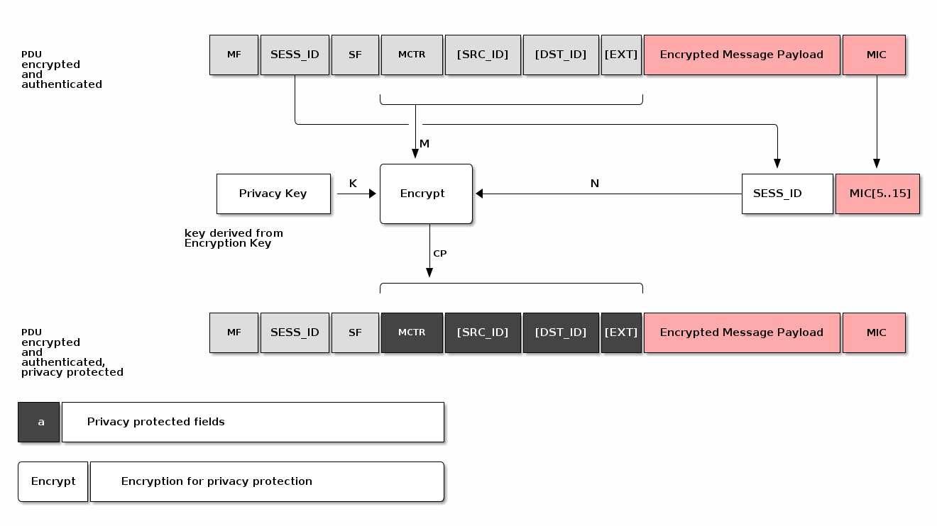
Figure 10. Matter Message Privacy
4.8.4. Privacy Processing of Incoming Messages
4.9. Message Exchanges
备注
An Exchange provides a way to group related messages together, organize communication flows, and enable higher levels of the communication stack to track semantically relevant groupings of messages.
The underlying session SHALL be one of the following session types:
1. secure unicast (as established by PASE or CASE)
2. unsecured (as is used for the initial session establishment phase of a PASE/CASE session)
3. secure group
4. MCSP
4.9.1. Exchange Role
The first Node to send a message in an Exchange is said to be in the
Initiator roleAll the other Nodes that subsequently participate in the Exchange are said to be in a
Responder role.
4.9.2. Exchange ID
Exchange ID field described in
Section 4.4.3.3, “Exchange ID (16 bits)”.The Exchange ID is allocated by the Initiator.
The Exchange is identified by the tuple
{Session Context, Exchange ID, Exchange Role}where Session Context is one of anUnsecured, Secured, Groupcast or MCSPsession context.
4.9.3. Exchange Context
An Exchange context is the metadata tracked for an Exchange by all exchange participants.
An Exchange context tracks the following data:
1. Exchange ID: The Exchange ID assigned by the Initiator
2. Exchange Role: Initiator or Responder
3. Session Context: The underlying Unsecured, Secured, Groupcast or MCSP session context
4.9.4. Exchange Message Dispatch
For the case of a first message, the Initiator creates a new Exchange.
The Node in the Initiator role SHALL always set the I Flag in the Exchange Flags of every message it sends in that Exchange.
Each Node in a Responder role SHALL use the Exchange ID received in previous messages.
Each Node in the Responder role SHALL NOT set the I Flag.
Each Node in a Responder role SHALL only set the Destination Node ID field to a value that identifies the Node in the Initiator role.
4.9.5. Exchange Message Processing
4.9.5.1. Exchange Message Matching
A given message is part of an Exchange if it satisfies all the following criteria:
1. The message was received over the session associated with the Exchange.
2. The Exchange ID of the message matches the Exchange ID of the Exchange,
3. The message has the I Flag set and the Exchange Role of the Exchange is Responder,
OR the message does not have the I Flag set and the Exchange Role of the Exchange is Initiator.
If the message does not match an existing Exchange, the message is considered an unsolicited message.
4.9.5.2. Unsolicited Message Processing
An unsolicited message is processed as follows:
1. If the unsolicited message is not marked as having a duplicate message counter,
    has a registered Protocol ID, and the I Flag is set:
    a. Create a new exchange from the incoming message.
    b. The new exchange will be used by the upper layer for
        generating responses and subsequent processing of the message.
2. Otherwise, if the message has the R Flag set:
    a. Create an ephemeral exchange from the incoming message
        and send an immediate standalone acknowledgement.
    b. The message SHALL NOT be forwarded to the upper layer,
        and excluding the sending of an immediate standalone acknowledgment, SHALL be ignored.
    c. The ephemeral exchange created for such duplicate or unknown messages
        with R Flag set is automatically closed in Section 4.11.5.2.2, “Standalone acknowledgement processing”.
3. Otherwise, processing of the message SHALL stop.
Creating an Exchange based on an Incoming Message:
a. The Exchange ID SHALL be set to the Exchange ID of the message.
b. The Exchange Role SHALL be set to the inverse of the incoming message I Flag
c. The Session Context SHALL be set to the Session on which the message was received.
A node SHOULD limit itself to a maximum of 5 concurrent exchanges over a unicast session. This is to prevent a node from exhausting the message counter window of the peer node.
4.9.5.3. Closing an Exchange
An Exchange MAY be closed by the application layer or a fatal connection error from the lower message layer.
The process of closing an Exchange follows:
1. Any pending acknowledgements associated with the Exchange SHALL be flushed.
    If there is a pending acknowledgment in the acknowledgement table for the Exchange
        and it has StandaloneAckSent set to false:
        a. Immediately send a standalone acknowledgement for the pending acknowledgement.
        b. Remove the acknowledgement table entry for the pending acknowledgement.
2. Wait for all pending retransmissions associated with the Exchange to complete.
    a. If the retransmission list for the Exchange is empty, remove the Exchange.
    b. Otherwise, leave the Exchange open and only close it
        once the retransmission list is empty.
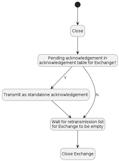
Figure 11. Exchange close flow
4.10. Secure Channel Protocol
Secure Channel Protocol defines the control plane for secure channel communication and security.
4.10.1. Secure Channel Protocol Messages
Secure Channel Protocol is composed of a collection of sub-protocols, including:
• Message Counter Synchronization Protocol (MCSP)
• Message Reliability Protocol (MRP)
• Passcode Based Session Establishment (PASE)
• Certificate Based Session Establishment (CASE)
Protocol Opcode |
Protocol Command Name |
|---|---|
0x00 |
MsgCounterSyncReq |
0x01 |
MsgCounterSyncRsp |
0x10 |
MRP Standalone Acknowledgement |
0x20 |
PBKDFParamRequest |
0x21 |
PBKDFParamResponse |
0x22 |
PASE Pake1 |
0x23 |
PASE Pake2 |
0x24 |
PASE Pake3 |
0x30 |
CASE Sigma1 |
0x31 |
CASE Sigma2 |
0x32 |
CASE Sigma3 |
0x33 |
CASE Sigma2_Resume |
0x40 |
StatusReport |
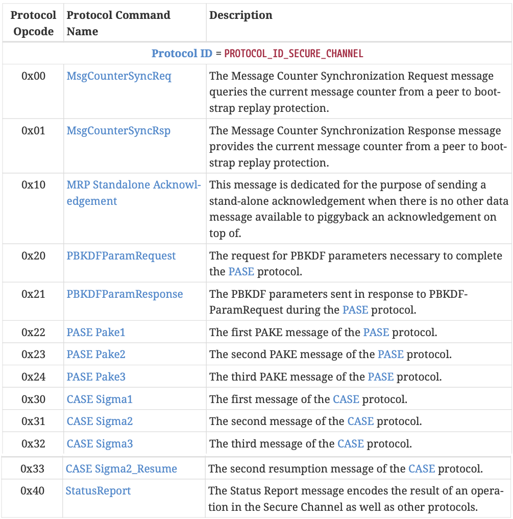
Table 17. Secure Channel Protocol Opcodes
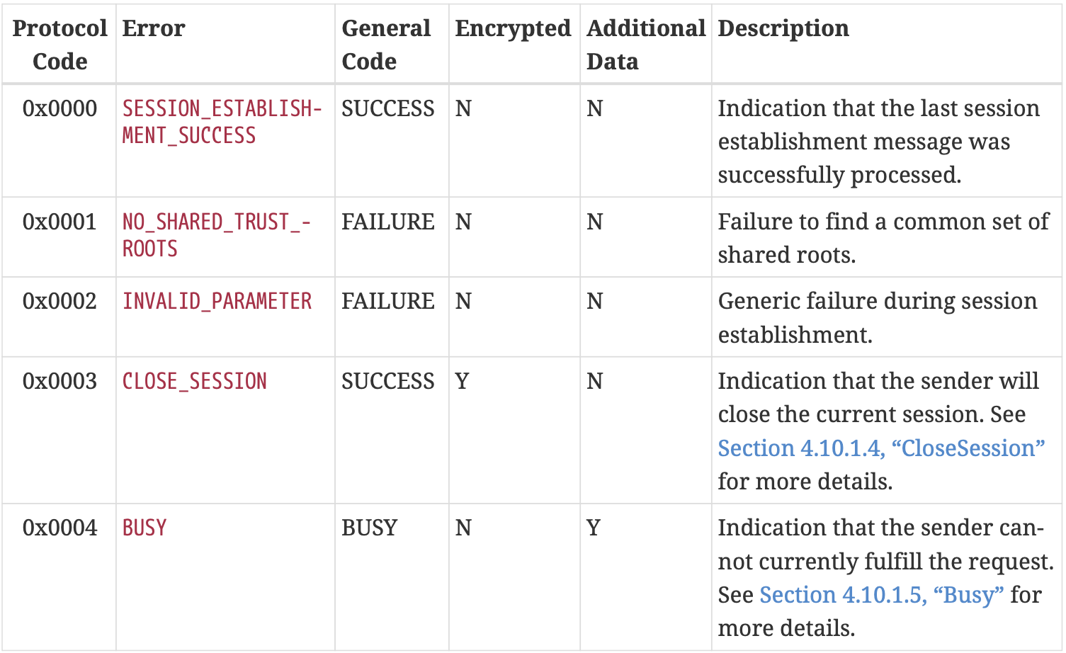
Table 18. Secure Channel Protocol Codes
4.10.2. Parameters and Constants
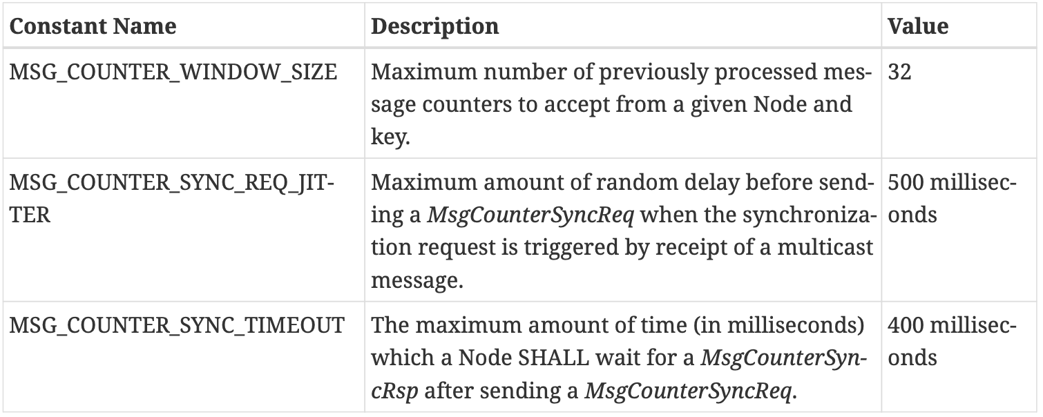
Table 19. Glossary of constants(MSG_COUNTER_WINDOW_SIZE, MSG_COUNTER_SYNC_REQ_JITTER, MSG_COUNTER_SYNC_TIMEOUT)
4.11. Message Reliability Protocol (MRP)
The protocol is optimized for constrained devices that may not be able to receive a message at the point it is due to be delivered to them.
Flow control mechanisms are not incorporated in MRP because it is intended to be used for short interactions with small numbers of messages in them.
4.11.1. Reliable Messaging Header Fields
The following fields are defined in the Exchange Flags for use exclusively by MRP:
• R Flag
• A Flag
• Acknowledged Message Counter
4.11.2. Reliable transfer
When the reliability bit is set, the reliable message is transmitted at most
MRP_MAX_TRANSMISSIONStimes until an acknowledgement of receipt is received from the peer or a timeout.
4.11.2.1. Retransmissions
Senders provide an automatic retransmission mechanism for reliable messages.
the sender SHALL trigger the automatic retry mechanism after a period of
mrpBackoffTimemilliseconds without receiving an acknowledgement
the duration of the retransmission timer SHALL be calculated as follows:
"mrpBackoffTime" = i * "MRP_BACKOFF_BASE"^(max(0,n-"MRP_BACKOFF_THRESHOLD"))
    * (1.0 + "random"(0,1) * "MRP_BACKOFF_JITTER")

mrpBackoffTime: the resultant retransmission timeout for this transmission
n: the number of send attempts before the current one for this message (0 if this is the initial transmission)
i: the base retry interval for the Exchange (either IDLE or ACTIVE)
    • If PeerActiveMode in the Session Context is true:
        ◦ i = SLEEPY_ACTIVE_INTERVAL of the peer
    • Else the peer is in idle mode:
        ◦ i = SLEEPY_IDLE_INTERVAL of the peer
4.11.2.2. Acknowledgements
4.11.3. Peer Exchange Management
The Reliable Messaging Protocol operates within the scope of an Exchange between two Nodes. MRP SHALL support one pending acknowledgement and one pending retransmission per Exchange.
4.11.4. Transport Considerations
When the upper layer requests a reliable message over a UDP transport, the R Flag SHALL be set on that message indicating that MRP SHALL be used.
Reliable messages sent over TCP or BTP SHALL utilize the underlying reliability mechanisms of those transports and SHOULD NOT set the R Flag.
4.11.5. Reliable Message Processing
4.11.5.1. Reliable Message Processing of Outgoing Messages
Piggyback acknowledgment processing:
1. Determine if there is a matching pending acknowledgement in the ``acknowledgement table``
    for the given message by checking all of the following conditions:
    Between given message and pending acknowledgement
    a. Destination Node Id and Exchange Id are the same
    b. AND either
        i. the Session Id and underlying Session Credentials are the same
        OR
        ii. both are of Unsecured Session Type.

2. If there is a matching pending acknowledgement,
    the A Flag SHALL be set on the outbound message so it will serve as a piggybacked acknowledgement.
    a. the Acknowledgment Message Counter field SHALL be set to
        the message counter of the received message for which an acknowledgement was pending.
    b. If the message being prepared is not a standalone acknowledgement,
        remove the matching entry from the acknowledgement table.
    c. If the message being prepared is a standalone acknowledgement,
        set the StandaloneAckSent field of the matching entry in the acknowledgement table to true.
Message retransmission processing:
1. If the outbound message is marked to be delivered reliably over a UDP transport,
    the R Flag SHALL be set on the given message to request an acknowledgement from the peer upon receipt.
2. Perform Section 4.6.1, “Message Transmission” processing step on the message to send the message to the peer:
3. If the transport interface returns an error on the send attempt,
    the error is assessed to determine whether the message can be retried.
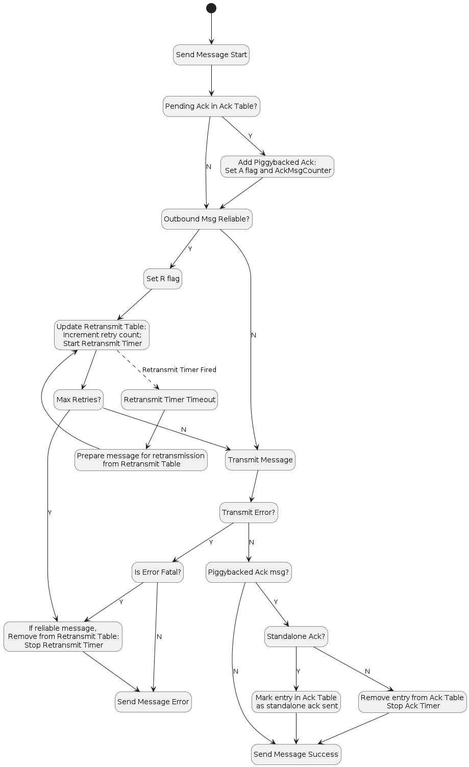
Figure 12. MRP send flow
4.11.5.2. Reliable Message Processing of Incoming Messages
A message received from Section 4.6.2, “Message Reception” for reliability processing SHALL be processed as follows:
1. Verify the message has a legal combination of reliability flags:
    a. Ifthe R Flag is set:
        i. If Group Session Type AND C Flag = 0, drop the message.
    b. If the A Flag is set:
        i. If Group Session Type AND C Flag = 0, drop the message.
2. Proceed to Section 4.9.5.1, “Exchange Message Matching”.
3. Proceed to Section 4.11.5.2.1, “Received acknowledgement processing”.
Received acknowledgement processing:
1. If the A Flag is set:
    a. Query the ``retransmission table`` for the Acknowledgement Message Counter contained in the received message.
        i. If there is a match:
            A. Remove the entry from the retransmission table.
            B. Stop the retransmission timer for that entry.
        ii. If there is no match, it indicates that this is either a duplicate acknowledgment
            or the Exchange context does not exist.
Standalone acknowledgement processing:
1. If the R Flag is set, the received message is requesting an acknowledgement be sent back:
    ...
2. The received message is then delivered to the next processing step of Section 4.6.2, “Message Reception”.
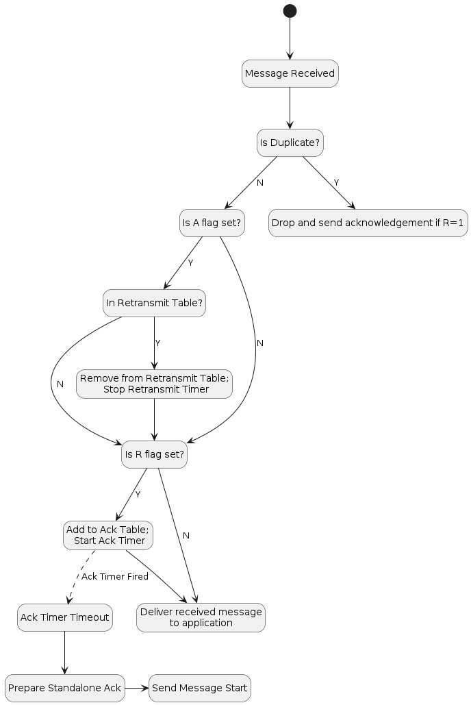
Figure 13. MRP receive flow
4.11.6. Reliable Message State
4.11.6.1. Retransmission Table
The sender maintains
context records containing information on all reliable messages sent that have acknowledgments still pending.
Each such reliable message context record includes the following fields:
• Reference to Exchange Context
• Message Counter
• Reference to fully formed, encoded and encrypted message buffer
• Send count
• Retransmission timeout counter
The message is sent a configurable maximum number of times (MRP_MAX_TRANSMISSIONS) and, if still undelivered, the application is notified of the failure.
4.11.6.2. Acknowledgement Table
The receiver maintains
context records containing information on all reliable messages sent that have acknowledgments still pending.
Each such reliable message context record includes the following fields:
• Reference to Exchange Context
• Message Counter
• A boolean, StandaloneAckSent
    indicating whether a standalone acknowledgement has been sent for this message counter.
    Initially false.
An entry SHALL remain in the table until one of the following things happens:
1. The exchange associated with the entry is closed. See Section 4.9.5.3, “Closing an Exchange”.
2. The exchange associated with the entry has switched to track a pending acknowledgement for a new message counter value.
    See Section 4.11.5.2.2, “Standalone acknowledgement processing”.
3. A message that is not a standalone acknowledgement is sent which serves as an acknowledgement for the entry.
    See Section 4.11.5.1.1, “Piggyback acknowledgment processing”.
4.11.7. MRP Messages
The MRP Standalone Acknowledgement message SHALL be formed as follows:
• The application payload SHALL be empty.
• The A Flag SHALL be set to 1.
• The Acknowledged Message Counter SHALL be included in the header.
• The Protocol ID SHALL be set to PROTOCOL_ID_SECURE_CHANNEL.
• The Protocol Opcode SHALL be set to MRP Standalone Acknowledgement.
4.11.8. Parameters and Constants
Parameter Name |
Default Value |
|---|---|
MRP_MAX_TRANSMISSIONS |
5 |
MRP_BACKOFF_BASE |
1.6 |
MRP_BACKOFF_JITTER |
0.25 |
MRP_BACKOFF_MARGIN |
1.1 |
MRP_BACKOFF_THRESHOLD |
1 |
MRP_STANDALONE_ACK_TIMEOUT |
200 milliseconds |
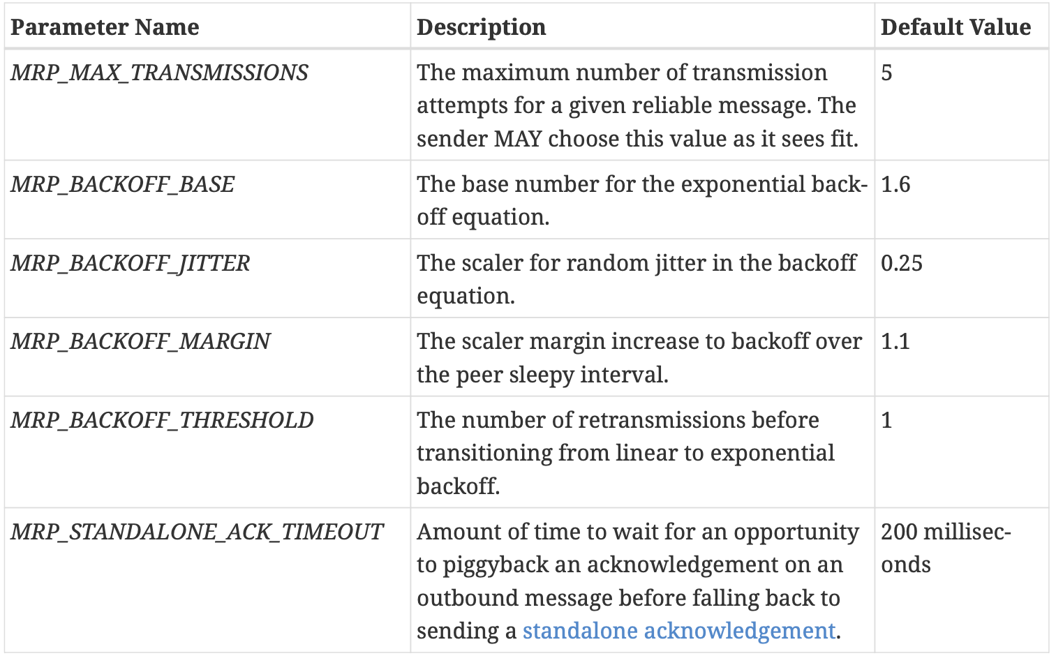
Table 21. Glossary of parameters
4.12. Unicast Communication
Unicast sessions exist in one of two phases:
1. Session Establishment Phase:
    A series of well-defined unencrypted messages that aim to establish a shared key.
2. Application Data Phase:
    A series of ad-hoc encrypted messages exchanging interaction model protocol actions,
    application data, etc.
4.12.1. Session Establishment Phase
Session establishment uses either the CASE or PASE protocol.
CASE SHALL be used as a session establishment mechanism for all sessions except: Communication for the purpose of commissioning when NOC has not yet been installed
PASE SHALL only be used for session establishment mechanism during device commissioning.
BTP MAY be used as the transport for device commissioning.
Unless otherwise specified, these SHALL be the only allowed unencrypted messages:
1. CASE
2. PASE
3. User-Directed Commissioning protocol
4. Secure Channel Status Report messages
This phase aims to:
1. Authenticate peers (CASE-based sessions only).
2. Derive shared secrets to encrypt subsequent session data.
3. Choose session identifiers to identify the subsequent session.
4.12.1.1. Unsecured Session Context
The following session context data SHALL be utilized to associate messages to a particular peer and recover context during unencrypted sessions:
1. Session Role:
    Records whether the node is the session `initiator` or `responder`.
2. Ephemeral Initiator Node ID:
    Randomly,
        selected for each session by the initiator from the `Operational Node ID range`,
        and
        enclosed by initiator as Source Node ID and responder as Destination Node ID.
            Initiators SHALL select a new random ephemeral node ID for each unsecured session,
                and SHALL not conflict with any other ephemeral node IDs
3. Message Reception State:
    Provides tracking for the Unencrypted Message Counter of the remote peer.
Matching and responder creation of Unsecured Session Contexts SHALL be as follows:
1. Given an incoming unencrypted message
    a. Locate any Unsecured Session Context with matching `Ephemeral Initiator Node ID`
        i. If any is located, the incoming message
            SHALL be assumed to be associated with this Unsecured Session Context
    b. Else if the message carries a Source Node ID
        i. Create a new Unsecured Session Context
        ii. Set Session Role to `responder`
        iii. Record the incoming message’s Source Node ID as `Ephemeral Initiator Node ID`
    c. Else discard the message
Initiator creation of Unsecured Session Contexts SHALL be as follows:
1. Given the first outgoing message of an unencrypted exchange
    a. Create a new Unsecured Session Context
    b. Set Session Role to `initiator`
    c. Randomly select a node ID from the `Operational Node ID range` that does not collide with
        any ephemeral node IDs for any other ongoing unsecured sessions opened by the initiator
        and record this as `Ephemeral Initiator Node ID`
4.12.1.2. Session Establishment over IP
When establishing a session over IP, the initiator SHALL use TCP when both of the following are true:
1. The initiator supports TCP
2. The responder supports TCP as indicated by the T flag
If one or both nodes do not support TCP, the initiator SHALL use MRP to establish the session.
4.12.1.4. Choosing Secure Unicast Session Identifiers
Both CASE and PASE allow each participant the ability to choose a unicast session identifier for the subsequent encrypted session. The session identifier SHALL be used to look up the relevant encryption keys and any other metadata for a particular session.
4.12.2. Application Data Phase
When the last CASE or PASE protocol message is sent or received and successfully processed, session establishment has completed.
4.12.2.1. Secure Session Context
the following conceptual session context data SHALL be utilized to securely process subsequent messages:
1. Session Type:
    Records whether the session was established using `CASE` or `PASE`.
2. Session Role:
    Records whether the node is the session `initiator` or `responder`.
3. Local Session Identifier:
    ◦ On a given Node, this is the identifier that SHALL be used to map
        from an incoming message’s Session ID field to the session context data.
4. Peer Session Identifier:
    ◦ On a given Node, this is the identifier that SHALL be used in the Session ID field of every outgoing message associated with the session,
        so that it can be interpreted as the Local Session Identifier by the remote peer.
5. I2RKey:
    Encrypts data in messages sent from the initiator of session establishment to the responder.
6. R2IKey:
    Encrypts data in messages sent from the session establishment responder to the initiator.
7. SharedSecret:
    Computed during the CASE protocol execution and re-used when CASE session resumption is implemented.
8. Local Message Counter:
    Secure Session Message Counter for outbound messages.
    ◦ At successful session establishment, it SHALL be initialized per `Section 4.5.1.1, “Message Counter Initialization”`.
9. Message Reception State:
    Provides tracking for the Secure Session Message Counter of the remote peer.
0. Local Fabric Index:
    Records the local Index for the session’s Fabric
1. Peer Node ID:
    Records the authenticated node ID of the remote peer, when available.
2. Resumption ID:
    The ID used when resuming a session between the local and remote peer.
3. SessionTimestamp:
    A timestamp indicating the time at which the last message was sent or received.
4. ActiveTimestamp:
    A timestamp indicating the time at which the last message was received.
The following sleepy parameters (see Table 5, “Glossary of parameters”):
a. SLEEPY_IDLE_INTERVAL
b. SLEEPY_ACTIVE_INTERVAL
c. PeerActiveMode:
    A boolean that tracks whether the peer node is in Active or Idle mode as defined in Section 2.9, “Sleepy End Device (SED)”.

PeerActiveMode is set as follows:
    PeerActiveMode = (now() - ActiveTimestamp) < "SLEEPY_ACTIVE_THRESHOLD"
4.13. Session Establishment
4.13.1. Passcode-Authenticated Session Establishment (PASE)
This section describes session establishment using a shared passcode together with an augmented Password-Authenticated Key Exchange (PAKE), in which only one party knows the passcode beforehand, to generate shared keys. This protocol is only used when commissioning a Node
4.13.1.1. Protocol Overview
The Passcode-Authenticated Session Establishment (PASE) protocol aims to establish the first session between a Commissioner and a Commissionee using a known passcode provided out-of-band.
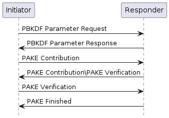
Figure 14. Overview of the PASE Protocol: The Commissioner is the Initiator and the Commissionee is the Responder.
4.13.1.2. Protocol Details
Table 22. PASE Messages
Message Name |
Payload TLV Encoding |
|---|---|
PBKDFParamRequest |
pbkdfparamreq-struct |
PBKDFParamResponse |
pbkdfparamresp-struct |
Pake1 |
pake-1-struct |
Pake2 |
pake-2-struct |
Pake3 |
pake-3-struct |
PakeFinished |
N/A (encoded via StatusReport) |
PBKDFParamRequest:
pbkdfparamreq-struct => STRUCTURE [ tag-order ]
{
    initiatorRandom    [1] : OCTET STRING [ length 32 ],
    initiatorSessionId [2] : UNSIGNED INTEGER [ range 16-bits ],
    passcodeId         [3] : UNSIGNED INTEGER [ length 16-bits ],
    hasPBKDFParameters [4] : BOOLEAN,
    initiatorSEDParams [5, optional] : sed-parameter-struct
}

1. SHALL generate a random number `InitiatorRandom = Crypto_DRBG(len = 32 \* 8)`.
2. SHALL generate a InitiatorSessionId for subsequent identification of this session.
3. SHALL choose a PasscodeId corresponding to a particular PAKE passcode verifier installed on the responder.
    A value of 0 is the default
4. SHALL indicate whether the PBKDF parameters (salt and iterations) are known
    for the particular passcodeId (for example from the QR code) by setting HasPBKDFParameters.
5. SHALL send a message with the appropriate Protocol Id and Protocol Opcode
PBKDFParamResponse:
pbkdfparamresp-struct => STRUCTURE [ tag-order ]
  {
    initiatorRandom    [1] : OCTET STRING [ length 32 ],
    responderRandom    [2] : OCTET STRING [ length 32 ],
    responderSessionId [3] : UNSIGNED INTEGER [ range 16-bits ],
    pbkdf_parameters   [4] : Crypto_PBKDFParameterSet,
    responderSEDParams [5, optional] : sed-parameter-struct
}

1. Verify passcodeID is set to 0.
2. Generate a random number `ResponderRandom = Crypto_DRBG(len = 32 \* 8)`.
3. Generate a ResponderSessionId for subsequent identification of this session.
4. Set the Peer Session Identifier in the Session Context
    to the value `PBKDFParamRequest.initiatorSessionId`.
5. Construct the appropriate `Crypto_PBKDFParameterSet` (PBKDFParameters).
6. Send a message with the appropriate Protocol Id and Protocol Opcode
Pake1:
pake-1-struct => STRUCTURE [ tag-order ]
{
    pA [1] : OCTET STRING [ length CRYPTO_PUBLIC_KEY_SIZE_BYTES ],
}

1. Set Peer SessionID in the Session Context to the value `PBKDFParamResponse.responderSessionId`
2. Generate the `Crypto_PAKEValues_Initiator` according to the `PBKDFParamResponse.pbkdf_parameters`
3. Using `Crypto_PAKEValues_Initiator`, generate `pA := Crypto_pA(Crypto_PAKEValues_Initiator)`
4. Send a message with the appropriate Protocol Id and Protocol Opcode
Pake2:
pake-2-struct => STRUCTURE [ tag-order ]
{
    pB [1] : OCTET STRING [ length CRYPTO_PUBLIC_KEY_SIZE_BYTES ],
    cB [2] : OCTET STRING [ length CRYPTO_HASH_LEN_BYTES],
}

1. Compute `pB := Crypto_pB(Crypto_PAKEValues_Responder)` using the passcode verifier indicated in `PBKDFParamRequest`
2. Compute `TT := Crypto_Transcript(PBKDFParamRequest, PBKDFParamResponse, Pake1.pA, pB)`
3. Compute `(cA, cB, Ke) := Crypto_P2(TT, Pake1.pA, pB)`
4. Send a message with the appropriate Protocol Id and Protocol Opcode
Pake3:
pake-3-struct => STRUCTURE [ tag-order ]
{
    cA [1] : OCTET STRING [length CRYPTO_HASH_LEN_BYTES],
}

1. Compute `TT := Crypto_Transcript(PBKDFParamRequest, PBKDFParamResponse, Pake1.pA, Pake2.pB)`
2. Compute `(cA, cB, Ke) := Crypto_P2(TT, Pake1.pA, Pake2.pB)`
3. Verify `Pake2.cB` against `cB`
4. Send a message with the appropriate Protocol Id and Protocol Opcode
PakeFinished:
1. Verify `Pake3.cA` against `cA`.
2. responder SHALL set SessionTimestamp to a timestamp from a clock which would
    allow for the eventual determination of the last session use relative to other sessions.
3. The responder SHALL encode and send PakeFinished.


The initiator SHALL set SessionTimestamp to a timestamp from a clock which would
    allow for the eventual determination of the last session use relative to other sessions.
Session Encryption Keys:
compute their sending and receiving session keys as described below:
    byte SEKeys_Info[] = /* "SessionKeys" */
            {0x53, 0x65, 0x73, 0x73, 0x69, 0x6f, 0x6e, 0x4b,
             0x65, 0x79, 0x73}
    I2RKey || R2IKey || AttestationChallenge =
      Crypto_KDF
      (
       inputKey = Ke,
       salt = [],
       info = SEKeys_Info,
       len = 3 * CRYPTO_SYMMETRIC_KEY_LENGTH_BITS
       )

1. Each key is exactly CRYPTO_SYMMETRIC_KEY_LENGTH_BITS bits.
2. The initiator SHALL use `I2RKey` to encrypt and integrity protect messages
    and the `R2IKey` to decrypt and verify messages.
3. The responder SHALL use `R2IKey` to encrypt and integrity protect messages
    and the `I2RKey` to decrypt and verify messages.
4. The `AttestationChallenge` SHALL only be used as a challenge during device attestation.
4.13.2. Certificate Authenticated Session Establishment (CASE)
certificate-authenticated session establishment (CASE) protocol using Node Operational credentials.
establishment mechanism
resumption mechanism
4.13.2.1. Protocol Overview
This session establishment protocol provides a means to:
1. Mutually authenticate both peer Nodes
2. Generate cryptographic keys to secure subsequent communication within a session
3. Exchange operational parameters for the session, such as Session Identifier and MRP parameters
The cryptographic protocol mirrors the [SIGMA] protocol and uses the Identity Protection Key (IPK) to provide better identity protection. Briefly, the protocol will:
1. Exchange ephemeral elliptic curve public keys to generate a shared secret
    (Sigma1.initiatorEphPubKey and Sigma2.responderEphPubKey)
2. Exchange certificates to prove identities
    (Sigma2.encrypted2.responderNOC and Sigma3.encrypted3.initiatorNOC)
3. Prove possession of the NOC private key by signing the ephemeral keys and NOC
    (sigma-2-tbsdata and sigma-3-tbsdata)
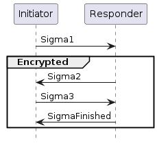
Figure 15. Basic Session Establishment: The basic protocol can be achieved within 2 round trips
4.13.2.2. Session Resumption
The protocol also provides a means to quickly resume a session using a previously established session.
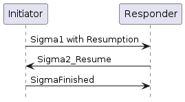
Figure 16. Session Resumption: Sigma1 message with both the optional resumptionID and initiatorResumeMIC fields
To perform session resumption, the following state from the previous session context must be known to the initiator and responder:
1. SharedSecret
2. Local Fabric Index
3. Peer Node ID
4. Peer CASE Authenticated Tags
5. ResumptionID
4.13.2.3. Protocol Details
Message format
Table 23. CASE Messages
Message Name |
Payload TLV Encoding |
|---|---|
Sigma1 |
sigma-1-struct |
Sigma2 |
sigma-2-struct, |
Sigma3 |
sigma-3-struct, |
Sigma2_Resume |
sigma-2-resume-struct, |
SigmaFinished |
N/A (encoded via StatusReport) |
Message Exchange
The
Sigma1,Sigma2,Sigma3, andSigmaFinishedof a distinct session establishment are part of the same message exchange.The
Sigma1 with resumption,Sigma2_ResumeandSigmaFinishedof a distinct session resumption are part of the same message exchange.The
Sigma1 with resumption,Sigma2,Sigma3andSigmaFinishedof a distinct session resumption that failed to perform the resumption are part of the same message exchange.
Generate and Send Sigma1
The initiator encodes and sends a Sigma1 message, with a payload that follows this TLV schema:
sigma-1-struct => STRUCTURE [ tag-order ]
{
  initiatorRandom    [1] : OCTET STRING [ length 32 ],
  initiatorSessionId [2] : UNSIGNED INTEGER [ range 16-bits ],
  destinationId      [3] : destination-identifier,
  initiatorEphPubKey [4] : ec-pub-key,
  initiatorSEDParams [5, optional] : sed-parameter-struct,
  resumptionID       [6, optional] : OCTET STRING [ length 16 ],
  initiatorResumeMIC [7, optional] : OCTET STRING [ length CRYPTO_AEAD_MIC_LENGTH_BYTES ]
}


1. SHALL generate a random number `InitiatorRandom = Crypto_DRBG(len = 32 \* 8)`.
2. SHALL generate a InitiatorSessionId for subsequent identification of this session.
3. SHALL generate a DestinationId to enable the responder to
        properly select a mutual Fabric and trusted root for the secure session.
4. SHALL generate an ephemeral key pair: `InitiatorEphKeyPair = Crypto_GenerateKeypair()`.
5. MAY encode any relevant MRP parameters.
6. Any context-specific tags not listed in the above TLV schemas SHALL be reserved for future use,
        and SHALL be silently ignored if seen by a responder which cannot understand them.
7. If the initiator is resuming a session
    a. Note the `ResumptionID` of the previous session.
    b. Generate the `S1RK` key.
    c. Generate the initiatorResumeMIC using the `SharedSecret` from the previous session
8. SHALL send a message with Secure Channel Protocol ID and Sigma1 Protocol Opcode
Msg1:
Msg1 = {
   initiatorRandom (1) = InitiatorRandom,
   initiatorSessionId (2) = InitiatorSessionId,
   destinationId (3) = DestinationId,
   initiatorEphPubKey (4) = InitiatorEphKeyPair.publicKey
   initiatorSEDParams (5) = sed-parameter-struct (optional),
   resumptionID (6) = ResumptionID (optional, only present if performing resumption),
   initiatorResumeMIC (7) = InitiatorResume1MIC (optional, only present if performing resumption)
 }
Validate Sigma1
On receipt of Msg1, the responder SHALL perform the following:
1. If Msg1 contains either a resumptionID or an initiatorResumeMIC field but not both
    SHALL send a status report: `StatusReport(GeneralCode: FAILURE, ProtocolId: SECURE_CHANNEL, ProtocolCode: INVALID_PARAMETER)`
    and perform no further processing.
2. Set the Peer Session Identifier in the Session Context to the value `Msg1.initiatorSessionId`.
3. If Msg1 contains both the resumptionID and initiatorResumeMIC fields
    SHALL search for an existing session that has a Resumption ID equal to the incoming resumptionID.
    If a single such session exists
        SHALL follow the steps in `Section 4.13.2.3.10, “Validate Sigma1 with Resumption”`
    Else
        continue the steps outlined in `Section 4.13.2.3.5, “Validate Sigma1 Destination ID”`.
4. If Msg1 does not contain a resumptionID and initiatorResumeMIC field,
    SHALL continue the steps in `Section 4.13.2.3.5, “Validate Sigma1 Destination ID”`.
Validate Sigma1 Destination ID
the responder:
1. SHALL validate the incoming destinationId
    a. SHALL traverse all its installed NOC, gathering the associated trusted roots' public keys from the associated chains
        and SHALL generate a `candidateDestinationId` for that tuple of `<Root Public Key, Fabric ID, Node ID>`.
    b. SHALL verify that the incoming `destinationId` matches one of the `candidateDestinationId` generated above.
        Upon such a match, the associated `trusted root, Fabric ID, Node ID and IPK` SHALL be recorded for subsequent use.
2. If there is no `candidateDestinationId` matching the incoming destinationId,
    SHALL send a status report: `StatusReport(GeneralCode: FAILURE, ProtocolId: SECURE_CHANNEL, ProtocolCode: NO_SHARED_TRUST_ROOTS)`
    and perform no further processing.
3. Otherwise, if a match was found for the destinationId,
    the matched `NOC`, `ICAC (if present)`, and `associated trusted root`
        SHALL be used for selection of the `responderNOC` and `responderICAC` in the steps for Sigma2.
Generate and Send Sigma2
If validation is successful, the responder encodes and sends a Sigma2 message:
sigma-2-tbsdata => STRUCTURE [ tag-order ]
{
    responderNOC       [1] : OCTET STRING,
    responderICAC      [2, optional] : OCTET STRING,
    responderEphPubKey [3] : ec-pub-key,
    initiatorEphPubKey [4] : ec-pub-key,
}
sigma-2-tbedata => STRUCTURE [ tag-order ]
{
    responderNOC  [1] : OCTET STRING,
    responderICAC [2, optional] : OCTET STRING,
    signature     [3] : ec-signature,
    resumptionID  [4] : OCTET STRING [ length 16 ],
}
sigma-2-struct => STRUCTURE [ tag-order ]
{
    responderRandom    [1] : OCTET STRING [ length 32 ],
    responderSessionId [2] : UNSIGNED INTEGER [ range 16-bits ],
    responderEphPubKey [3] : ec-pub-key,
    encrypted2         [4] : OCTET STRING,
    responderSEDParams [5, optional] : sed-parameter-struct
}
备注
sigma-2-tbsdata is NOT transmitted but is instead signed; the signature will be encrypted and transmitted.
The responder:
1. SHALL generate a random resumption ID `ResumptionID = Crypto_DRBG(len = 16 \* 8)`.
2. SHALL use the Node Operational Key Pair `ResponderNOKeyPair`, `responderNOC`, and `responderICAC`(if present) corresponding to the NOC
3. SHALL generate an ephemeral key pair `ResponderEphKeyPair = Crypto_GenerateKeypair()`.
4. SHALL generate a shared secret:
    SharedSecret = Crypto_ECDH(
         privateKey = ResponderEphKeyPair.privateKey,
         publicKey = Msg1.initiatorEphPubKey,
    )
5. SHALL encode the following items as a `sigma-2-tbsdata` with an anonymous tag:
    a. responderNOC as a matter-certificate
    b. responderICAC (if present) as a matter-certificate
    c. ResponderEphKeyPair.publicKey
    d. Msg1.initiatorEphPubKey
    e. ResumptionID
6. SHALL generate a signature:
    TBSData2Signature = Crypto_Sign(
         message = sigma-2-tbsdata,
         privateKey = ResponderNOKeyPair.privateKey
    )
7. SHALL encode the following items as a sigma-2-tbedata
    a. responderNOC
    b. responderICAC (if present)
    c. TBSData2Signature
8. SHALL generate the `S2K key`
9. SHALL generate the encrypted and integrity protected data:
    byte TBEData2_A[] = {}
    byte TBEData2_Nonce[13] = /* "NCASE_Sigma2N" */
        {0x4e, 0x43, 0x41, 0x53, 0x45, 0x5f, 0x53, 0x69,
         0x67, 0x6d, 0x61, 0x32, 0x4e}
    TBEData2Encrypted = Crypto_AEAD_GenerateEncrypt(
      K = S2K,
      P = TBEData2,
      A = TBEData2_A,
      N = TBEData2_Nonce
    )
0. SHALL generate a random number `Random = Crypto_DRBG(len = 32 * 8)`.
1. SHALL generate a ResponderSessionId for subsequent identification of this secured session.
2. SHALL use the Fabric IPK
3. Any context-specific tags not listed in the above TLV schemas
    SHALL be reserved for future use, and SHALL be silently ignored if seen by an initiator which cannot understand them.
4. SHALL send a message with Secure Channel Protocol ID and Sigma2 Protocol Opcode
Msg2:
Msg2 = {
   responderRandom (1) = Random,
   responderSessionId (2) = ResponderSessionId,
   responderEphPubKey (3) = ResponderEphKeyPair.publicKey,
   encrypted2 (4) = TBEData2Encrypted,
   responderSEDParams (5) = sed-parameter-struct (optional)
}
Validate Sigma2
On receipt of Msg2, the initiator SHALL perform the following:
1. SHALL generate a shared secret:
    SharedSecret = Crypto_ECDH(
         privateKey = InitiatorEphKeyPair.privateKey,
         publicKey = Msg2.responderEphPubKey,
    )
2. SHALL generate the S2K key.
3. SHALL generate the decrypted data:
    byte TBEData2_A[] = {}
    byte TBEData2_Nonce[13] = /* "NCASE_Sigma2N" */
           {0x4e, 0x43, 0x41, 0x53, 0x45, 0x5f, 0x53, 0x69,
            0x67, 0x6d, 0x61, 0x32, 0x4e}
    Success, TBEData2 = Crypto_AEAD_DecryptVerify(
         K = S2K,
         C = Msg2.encrypted2,
         A = TBEData2_A,
         N = TBEData2_Nonce
    )
4. If the value of Success is FALSE,
    SHALL send a status report: `StatusReport(GeneralCode: FAILURE, ProtocolId: SECURE_CHANNEL, ProtocolCode: INVALID_PARAMETER)`
    and perform no further processing.
5. SHALL verify that the `NOC` in `TBEData2.responderNOC` and `ICAC` in `TBEData2.responderICAC` (if present) fulfills the following constraints:
6. If any of the validations from the previous step fail,
    SHALL send a status report: `StatusReport(GeneralCode: FAILURE, ProtocolId: SECURE_CHANNEL, ProtocolCode: INVALID_PARAMETER)`
    and perform no further processing.
7. SHALL verify `TBEData2.responderNOC` using:
8. If the value of Success is FALSE, ...
9. SHALL encode the following items as a sigma-2-tbsdata with an anonymous tag:
0. SHALL verify TBEData2.signature (see RFC 5280):
1. If the value of Success is FALSE, ...
2. Set the Resumption ID in the Session Context to the value TBEData2.resumptionID.
3. Set the Peer Session Identifier in the Session Context to the value Msg2.responderSessionId.
Generate and Send Sigma3
If validation is successful, the initiator encodes and sends a Sigma3 message:
sigma-3-tbsdata => STRUCTURE [ tag-order ]
{
    initiatorNOC       [1] : OCTET STRING,
    initiatorICAC      [2, optional] : OCTET STRING,
    initiatorEphPubKey [3] : ec-pub-key,
    responderEphPubKey [4] : ec-pub-key,
}
sigma-3-tbedata => STRUCTURE [ tag-order ]
{
    initiatorNOC  [1] : OCTET STRING,
    initiatorICAC [2, optional] : OCTET STRING,
    signature     [3] : ec-signature,
}
sigma-3-struct => STRUCTURE [ tag-order ]
{
    encrypted3 [1] : OCTET STRING,
}
The initiator SHALL:
1. SHALL select
        its Node Operational Key Pair `InitiatorNOKeyPair`,
        Node Operational Certificates `initiatorNOC`
        and `initiatorICAC` (if present),
        and Trusted Root CA Certificate `TrustedRCAC`
    corresponding to the chosen Fabric as determined by the Destination Identifier from Sigma1.
2. SHALL encode the following items as a sigma-3-tbsdata with an anonymous tag:
    a. initiatorNOC as a matter-certificate
    b. initiatorICAC (if present) as a matter-certificate
    c. InitiatorEphKeyPair.publicKey
    d. Msg2.responderEphPubKey
3. SHALL generate a signature:
    TBSData3Signature = Crypto_Sign(
         message = sigma-3-tbsdata,
         privateKey = InitiatorNOKeyPair.privateKey
    )
4. SHALL encode the following items as a sigma-3-tbedata:
5. SHALL generate the S3K key.
6. SHALL generate the encrypted and integrity protected data:
    byte TBEData3_A[] = {}
    byte TBEData3_Nonce[13] = /* "NCASE_Sigma3N" */
       {0x4e, 0x43, 0x41, 0x53, 0x45, 0x5f, 0x53, 0x69,
        0x67, 0x6d, 0x61, 0x33, 0x4e}
    TBEData3Encrypted = Crypto_AEAD_GenerateEncrypt(
         K = S3K,
         P = TBEData3,
         A = TBEData3_A,
         N = TBEData3_Nonce
    )
7. Any context-specific tags not listed in the above TLV schemas SHALL be reserved for future use
8. SHALL send a message with Secure Channel Protocol ID and Sigma3 Protocol Opcode
9. SHALL generate the session encryption keys using the method described in `Section 4.13.2.6.6, “Session Encryption Keys”`.
Validate Sigma3
On receipt of Msg3, the responder SHALL perform the following:
1. SHALL generate the S3K key.
2. SHALL generate the decrypted data:
    byte TBEData3_A[] = {}
    byte TBEData3_Nonce[13] = /* "NCASE_Sigma3N" */
        {0x4e, 0x43, 0x41, 0x53, 0x45, 0x5f, 0x53, 0x69,
         0x67, 0x6d, 0x61, 0x33, 0x4e}
    Success, TBEData3 = Crypto_AEAD_DecryptVerify(
      K = S3K,
      C = Msg3.encrypted3,
      A = TBEData3_A,
      N = TBEData3_Nonce
    )
3. If the value of Success is FALSE, ...
4. SHALL verify that the NOC in TBEData3.responderNOC and the ICAC in TBEData3.responderICAC fulfill the following constraints:
5. If any of the validations from the previous step fail, ...
6. SHALL verify TBEData3.initiatorNOC using:
7. If the value of Success is FALSE,
8. SHALL encode the following items as a sigma-3-tbsdata with an anonymous tag:
9. SHALL verify TBEData3.signature (see RFC 5280):
    Success = Crypto_Verify(
        publicKey= public key obtained from initiatorNOC,
        message = sigma-3-tbsdata,
        signature = TBEData3.signature
    )
0. If the value of Success is FALSE,
1. SHALL generate the session keys
2. SHALL initialize its Local Message Counter
3. SHALL initialize the Message Reception State
4. SHALL set SessionTimestamp to a timestamp from a clock
    which would allow for the eventual determination of the last session use relative to other sessions.
5. SHALL encode and send SigmaFinished.
Validate Sigma1 with Resumption
todo
Generate and Send Sigma2_Resume
todo
Validate Sigma2_Resume
todo
SigmaFinished
To indicate the successful completion of the protocol, the Node receiving Sigma3 (if a new session is being established) or Sigma2_Resume (if a session is being resumed) SHALL send a status report: StatusReport(GeneralCode: SUCCESS, ProtocolId: SECURE_CHANNEL, ProtocolCode: SESSION_ESTABLISHMENT_SUCCESS).
On successful receipt of SigmaFinished, The receiving node SHALL:
1. SHALL initialize the `Local Message Counter` for the newly established secure session whose success is acknowledged by this message.
2. SHALL set `SessionTimestamp` to a timestamp from a clock
    which would allow for the eventual determination of the last session usage relative to other sessions.
If this message is received out-of-order or unexpectedly, then it SHALL be ignored.
4.13.2.4. Field Descriptions
Destination Identifier:
destination-identifier => OCTET STRING [length CRYPTO_HASH_LEN_BYTES]
A destination identifier is generated by:
1. Concatenating the following octet strings for subsequent usage as a destinationMessage:
    initiatorRandom
    rootPublicKey
    fabricId
    nodeId
2. Obtaining the appropriate Identity Protection Key (IPK)
3. Computing an identifier destinationIdentifier of length `CRYPTO_HASH_LEN_BYTES` using `Crypto_HMAC()` with
    the `IPK` as the key and `destinationMessage` as the message

steps can be summarized as:
  destinationMessage = initiatorRandom || rootPublicKey || fabricId || nodeId
  destinationIdentifier = Crypto_HMAC(key=IPK, message=destinationMessage)
For example:
1. Root public key for the common Fabric, in uncompressed elliptical curve point form:
    RootPublicKey := // Raw uncompressed point form
      04:4a:9f:42:b1:ca:48:40:d3:72:92:bb:c7:f6:a7:e1:
      1e:22:20:0c:97:6f:c9:00:db:c9:8a:7a:38:3a:64:1c:
      b8:25:4a:2e:56:d4:e2:95:a8:47:94:3b:4e:38:97:c4:
      a7:73:e9:30:27:7b:4d:9f:be:de:8a:05:26:86:bf:ac:
      fa
2. Common Fabric ID of 0x2906_C908_D115_D362 scalar (octets "62:d3:15:d1:08:c9:06:29" in little- endian)
3. Desired Destination Node ID of 0xCD55_44AA_7B13_EF14 (octets "14:ef:13:7b:aa:44:55:cd" in little-endian)
4. Identity Protection Key Epoch Key value of:
    IPKEpochKey := 4a:71:cd:d7:b2:a3:ca:90:24:f9:6f:3c:96:a1:9d:ee
    =>
    IPK := 9b:c6:1c:d9:c6:2a:2d:f6:d6:4d:fc:aa:9d:c4:72:d4
5. Initiator Random value of:
    7e:17:12:31:56:8d:fa:17:20:6b:3a:cc:f8:fa:ec:2f:
    4d:21:b5:80:11:31:96:f4:7c:7c:4d:eb:81:0a:73:dc


=> DestinationMessage octets:
  7e:17:12:31:56:8d:fa:17:20:6b:3a:cc:f8:fa:ec:2f:
  4d:21:b5:80:11:31:96:f4:7c:7c:4d:eb:81:0a:73:dc:
  04:4a:9f:42:b1:ca:48:40:d3:72:92:bb:c7:f6:a7:e1:
  1e:22:20:0c:97:6f:c9:00:db:c9:8a:7a:38:3a:64:1c:
  b8:25:4a:2e:56:d4:e2:95:a8:47:94:3b:4e:38:97:c4:
  a7:73:e9:30:27:7b:4d:9f:be:de:8a:05:26:86:bf:ac:
  fa:62:d3:15:d1:08:c9:06:29:14:ef:13:7b:aa:44:55:
  cd
=> DestinationIdentifier octets:
  dc:35:dd:5f:c9:13:4c:c5:54:45:38:c9:c3:fc:42:97:
  c1:ec:33:70:c8:39:13:6a:80:e1:07:96:45:1d:4c:53
Public Key
A public key ec-pub-key is the byte string representation of an uncompressed elliptic curve point as defined in section 2.3.3 of SEC1:
ec-pub-key => OCTET STRING [ length CRYPTO_PUBLIC_KEY_SIZE_BYTES ]
4.13.2.5. Signature
An ec-signature is the encoding of the signature as defined in Section 3.5.3, “Signature and verification”:
ec-signature => OCTET STRING [ length (CRYPTO_GROUP_SIZE_BYTES * 2) ]
4.13.2.6. Cryptographic Keys
Identity Protection Key (IPK)
Sigma2 Key (S2K)
Sigma3 Key (S3K)
Sigma1 Resumption Key
Sigma2 Resumption Key
Session Encryption Keys
Resumption Session Encryption Keys
4.13.2.7. Session Context Storage
After the session is established successfully at both peers, some fields SHALL be recorded in the secure session context for later use:
1. The peer NOC's matter-node-id
2. Fabric References and Fabric Identifier
3. All peer NOC's case-authenticated-tag
4.13.2.8. Minimal Number of CASE Sessions
A node SHALL support at least 3 CASE session contexts per fabric.(Device type specifications MAY require a larger minimum.)
a minimum number it defines is a per-fabric minimum.
Example: If a device type requires at least 4 CASE session contexts, and a node supports 7 fabrics, the node would support at least 28 CASE session contexts, and ensure that each fabric could use at least 4 of them.
4.14. Group Communication
4.14.1. Groupcast Session Context
Groupcast sessions are conceptually long-running, lasting the duration of a node’s membership in a group.
Group membership is tracked in the Group Key Management Cluster.
Groupcast Session Context:
1. Fabric Index
2. Group ID
3. Source Node ID
4. Source IP Address
5. Source Port
6. Operational Group Key
7. Group Session ID
Once a
Groupcast Session Contextwith trust-first policy is created to track authenticated messages from a given Source Node ID, that record SHALL NOT be deleted or recycled until the node reboots.This is to prevent replay attacks that first exhaust the memory allocated to group session counter tracking and then inject older messages as valid, and enforces that trust-first authentication works as intended within the full duration of a boot cycle.
Any message from a source that cannot be tracked SHALL be dropped.
4.14.2. Sending a group message
To prepare a multicast message to a Group ID with a given GroupKeySetID and IPv6 hop count parameter, the Node SHALL:
1. Obtain, for the given GroupKeySetID, and the associated Group Session ID.
    GroupKeySetID: the current Operational Group Key as the Encryption Key,

2. Perform `Section 4.6.1, “Message Transmission”` processing steps on the message with the following arguments:
    a. The Destination Node Id argument SHALL be the Group Node Id corresponding to the given Group ID.
    b. The Session Id argument SHALL be the Group Session ID from step 1.
    c. The Security Flags SHALL have only the `P Flag` set.
    d. The transport SHALL be a site-local routable IPv6 interface.
Next, prepare the message as an IPv6 packet:
1. Set the private, secured message from step 2 above as the IPv6 payload.
2. Set the IPv6 hop count to the value given.
3. Set the IPv6 destination to the `Section 2.5.6.2, “IPv6 Multicast Address”`
    based on the provided destination Group ID, Fabric ID,
    and `Section 11.2.6.2.9, “GroupKeyMulticastPolicy”` of the group key.
4. Set the IPv6 source to an operational IPv6 Unicast Address of the sending Node.
5. Set the IPv6 UDP port number to the Matter IPv6 multicast port.
4.14.3. Receiving a group message
All Nodes supporting groups SHALL register to receive on the associated IPv6 multicast address, at the Matter IPv6 multicast port, for each group of which they are a member.
The Node SHALL:
1. Extract the message from the IPv6 payload.
2. Perform `Section 4.6.2, “Message Reception”` processing steps on the message.
4.15. Group Key Management
This section describes
operational group keys, a mechanism forgenerating,disseminatingandmanagingshared symmetric keys across a group of Nodes in a Fabric.Operational group keysare made available to applications for the purpose of authenticating peers, securing group communications, and encrypting data.
These keys allow Nodes to:
• Prove to each other that they are members of the associated group
• Exchange messages confidentially,
    and without fear of manipulation by non-members of the group
• Encrypt data in such a way that
    it can only be decrypted by other members of the group
A central feature of
operational group keysis the ability to limit access to keys to a trusted set of Nodes.credentials (required to generate
operational group keys)SHALL only be accessible to Nodes with a certain level of privilege — those deemed a member of the group.Operational group keysare shareable across all types and combinations of Nodes as determined by the Administrator managing the group.It is the responsibility of the Administrator managing the group.
4.15.1. Operational Groups
An operational group is a logical collection of Nodes that are running one or more common application clusters and share a common security domain in the form of a shared, symmetric group key.
Multiple operational groups MAY share the same operational group key, and thus be used to create logical subgroups over a shared security domain.
4.15.2. Operational Group Key Derivation
An
operational group keyis a symmetric key used as the Encryption Key during Message Processing for group communication.An
operational group keyis produced by applying a key derivation function with an epoch key and salt value as inputs as follows:OperationalGroupKey = Crypto_KDF ( InputKey = `Epoch Key`, Salt = `CompressedFabricIdentifier`, Info = "GroupKey v1.0", Length = CRYPTO_SYMMETRIC_KEY_LENGTH_BITS ) The `Info` is specified in `Section 4.15.2.1, “Group Security Info”`. The `Salt` is specified in `Section 4.3.2.2, “Compressed Fabric Identifier”`.
For example:
• An Epoch Key value of: 23:5b:f7:e6:28:23:d3:58:dc:a4:ba:50:b1:53:5f:4b
• A CompressedFabricIdentifier value of: 87:e1:b0:04:e2:35:a1:30
=>
resulting operational group key: a6:f5:30:6b:af:6d:05:0a:f2:3b:a4:bd:6b:9d:d9:60
Group membership is enforced by limiting access to the epoch keys.
Only Nodes that possess the input epoch key can derive a given operational key.
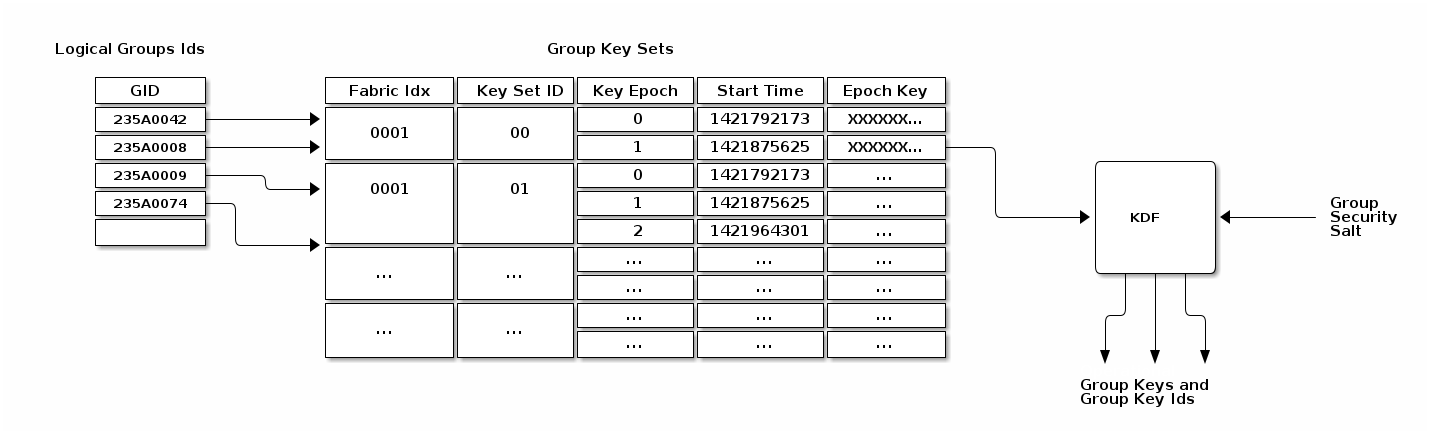
Figure 17. Group Key Derivation
4.15.2.1. Group Security Info
A hard-coded
group security infois used to diversify the set of operational group keys.This value is hard-coded into the standard’s implementation, and thus is distributed with the associated code.
4.15.2.2. Group Key Set
A
group key setlimits the key derivation process to Nodes within the respective operational groups.Access to a
group key setis limited based on the functionality provided by a Node and/or the privilege afforded to it.For example, certain home security devices, such as a security system or door lock, may have access to a “Physical Access”
group key set, while devices such as light bulbs or window coverings would not.Operational
group key lifetimeis limited by assigning an expiration time to eachepoch keyin a givengroup key set.By constraining the validity of a given epoch key to an epoch, the ability for members to derive and operate with an operational group key can be constrained to particular periods of time.
4.15.3. Epoch Keys
Each key SHALL be a random value of length CRYPTO_SYMMETRIC_KEY_LENGTH_BITS bits:
EpochKey = Crypto_DRBG(len = CRYPTO_SYMMETRIC_KEY_LENGTH_BITS)
4.15.3.1. Using Epoch Keys
Nodes sending group messages SHALL use
operational group keysthat are derived from the currentepoch key(specifically, the epoch key with the latest start time that is not in the future).Nodes receiving group messages SHALL accept the use of any key derived from one of the currently
installed epoch keys.
4.15.3.2. Managing Epoch Keys
The epoch keys are managed using the
Group Key Management Cluster.For every group key set published by the key distribution Administrator, there SHALL be at least 1 and at most 3 epoch keys in rotation.
Key updates are idempotent operations: Any epoch key update MAY deliver a partial key set but SHALL include EpochKey0 and MAY include EpochKey1 and EpochKey2. Any update of the key set, including a partial update, SHALL remove all previous keys in the set, however many were defined.
4.15.3.3. Epoch Key Rotation
The key distribution Administrator generates new
epoch keyson a regular basis, giving each a unique id and adding them to the list of existing epoch keys within a group.The start time for each new epoch key is scheduled to occur after a configurable key propagation interval.
The propagation interval is set sufficiently large such that the Administrator can synchronize all Nodes in the operational group with the new epoch key list within that time.
4.15.3.4. Epoch Key Rotation without Time Synchronization
This scheme requires the Node to receive epoch keys from the key distribution Administrator at a rate that is at least as fast as the configured key propagation interval.
The key distribution Administrator SHOULD update
all Nodes without time, such as SEDs, before the new epoch key is activated, and then letNodes with timeall roll to the new epoch key at the synchronized start time.
4.15.3.5. Epoch Key Rotation logic
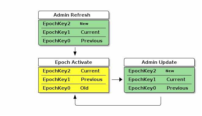
Figure 18. Epoch Key Rotation
For each epoch key slot, the start time of the key is shown as one of the following values:
• New - a key with a start time in the future.
• Current - the active key with the newest start time.
• Previous - the active key with the second newest start time.
• Old - an active key with the third newest start time.
The diagram shows two types of state transitions:
1. Admin Update -
    an update of an old key by the Administrator.
    Changes made during this state transition are indicated in green.
2. Epoch Activate -
    activation of an epoch key due to system time becoming greater than the start time.
    Changes during this state transition are indicated in yellow.
4.15.3.6. Group Session ID
A Group Session ID is a special case of a 16-bit Session ID that is specifically used for group communication.
GroupKeyHash =
    Crypto_KDF
    (
        InputKey = OperationalGroupKey,
        Salt = [],
        Info = "GroupKeyHash",
        Length = 16  // Bits
   )

// GroupKeyHash is an array of 2 bytes (16 bits) per Crypto_KDF
// GroupSessionId is computed by considering the GroupKeyHash as a Big-Endian value.

GroupSessionId = (GroupKeyHash[0] << 8) | (GroupKeyHash[1] << 0)
For example:
An Operational Group Key value of: `a6:f5:30:6b:af:6d:05:0a:f2:3b:a4:bd:6b:9d:d9:60`
=>
• Raw output of GroupKeyHash: `b9:f7`
• Group Session ID scalar value to be used for further processing: `0xB9F7` (47607 decimal)
4.15.4. Distribution of Key Material
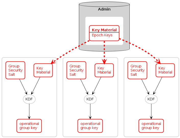
Figure 19. Group Key Distribution
4.15.4.1. Installing a Group onto a Newly Commissioned Node
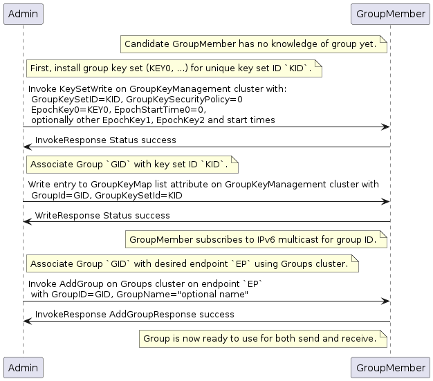
Figure 20. Installing a group onto a new node
Sequence:
• Admin:
    ◦ Generate fabric-unique group ID `GID` and random key `key0` for group key set ID `K`.
    ◦ Write the group key set `K` to the remote node, GroupMember, using KeySetWrite command.
    ◦ Associate `GID` with key set `K` by writing an entry to the GroupKeyMap list attribute.

• GroupMember:
    ◦ Node subscribes to the IPv6 multicast address generated from the `fabric ID` and `group ID`.

• Admin:
    ◦ Associate `endpoint` with `GID` by sending the Groups cluster’s AddGroup command to endpoint.
4.16. Message Counter Synchronization Protocol(MCSP)
This section describes the protocol used to securely synchronize the message counter used by a sender of messages encrypted with a symmetric group key.
Message counter synchronization is an essential part of enabling secure messaging between members of an operational group.
Specifically, it protects against replay attacks
4.16.1. Message Counter Synchronization Methods
4.16.1.1. Trust-first policy
All control messages (any message with C Flag set) use the control message counter and SHALL use Trust-first for synchronization.
Note that MCSP is not used for Trust-first synchronization.
备注
This policy provides lower latency for less security-sensitive applications such as lighting.
4.16.1.2. Cache-and-sync policy
The message that triggers message counter synchronization is stored, a message counter synchronization exchange is initiated, and only when the synchronization is completed is the original message processed.
Support for the cache-and-sync policy and MCSP is optional.
备注
Cache-and-sync provides replay protection even in the case where a Node has been rebooted, at the expense of higher latency.
4.16.2. Group Peer State
For every peer node id the following information is available in the Group Peer State Table:
• Peer’s Encrypted Group Data Message Counter Status:
    ◦ Synchronized Data Message Counter
    ◦ Flag to indicate whether this counter value is valid and synchronized.
    ◦ The message reception state bitmap tracking the recent window
        of data message counters received from the peer.

• Peer’s Encrypted Group Control Message Counter Status:
    ◦ Synchronized Control Message Counter
    ◦ Flag to indicate whether this counter value is valid and synchronized.
    ◦ The message reception state bitmap tracking the recent window
        of control message counters received from the peer.
There are three scenarios where the receiver of an encrypted message does not know the sender’s last message counter:
• The encrypted message is the first received from a peer.
• The device rebooted without persisting the Group Peer State Table content.
• The entry for the Peer in the Group Peer State Table
    was expunged due to the table being full.
4.16.3. MCSP Messages
4.16.3.1. MsgCounterSyncReq - Message Counter Synchronization Request
MsgCounterSyncReqmessage is sent when a message was received from a peer whose current message counter is unknown.A
MsgCounterSyncReqmessage SHALL be secured with thegroup keyfor which counter synchronization is requested
Table 24. Message Counter Sync Request:
Challenge: 8 bytes, 64-bit random number generated using the DRBG
4.16.3.2. MsgCounterSyncRsp - Message Counter Synchronization Response
MsgCounterSyncRspmessage is sent in response to aMsgCounterSyncReq.
Table 25. Message Counter Sync Response:
Synchronized Counter: 4 bytes
    The current data message counter for the node sending this resp.
Response: 8 bytes
    Response SHALL be the same as the 64-bit value sent in the Challenge field
4.16.4. Unsynchronized Message Processing
An unsynchronized message is one that is cryptographically verified from a node whose message counter is unknown.
Upon receipt of an unsynchronized message process the message as follows:
1. The message SHALL be of Group Session Type, otherwise discard the message.
2. If C Flag is set to 1:
    a. Create a Message Reception State and set its `max_message_counter`
        to the message counter of the given message, i.e. `trust-first`.
    b. Accept the message for further processing.
3. If C Flag is set to 0:
    a. Determine the `Section 11.2.6.2.2, “GroupKeySecurityPolicy”` of the `operational group key` used to authenticate the message.
    b. If the key has a trust-first security policy, the receiver SHALL:
        i. Set the peer’s `group key data message counter` to Message Counter of the message.
            A. Clear the Message Reception State bitmap for the group session from the peer.
            B. Mark the peer's group key data message counter as synchronized.
        ii. Process the message.
    c. If the key has a cache-and-sync security policy, the receiver SHALL:
        i. If MCSP is not in progress for the given peer Node ID and group key:
            A. Store the message for later processing.
            B. Proceed to `Section 4.16.5, “Message Counter Synchronization Exchange”`.
        ii. Otherwise, do not process the message.
            A. An implementation MAY queue the message for later processing
                after MCSP completes if resources allow.
4.16.5. Message Counter Synchronization Exchange
A message synchronization exchange starts by sending the
MsgCounterSyncReqmessage to the peer Node that sent the message with unknown message counter.When a synchronization request is triggered by an incoming multicast message, the Node SHALL first wait for a uniformly random amount of time between 0 and
MSG_COUNTER_SYNC_REQ_JITTER.
The sender of the MsgCounterSyncReq message SHALL:
1. Set the Message Header fields
2. Create a new synchronization Exchange
3. Set the Challenge field to the value returned by Crypto_DRBG(len = 8 \* 8)
    and store that value to resolve synchronization responses from the destination peer.
4. Arm a timer to enforce that a synchronization response is received before `MSG_COUNTER_SYNC_TIMEOUT`.
5. Invoke `Section 4.6.1, “Message Transmission”` using parameters from step 1 to encrypt
    and then send the request message over UDP to the IPv6 unicast address of the destination.
The receiver of MsgCounterSyncReq SHALL:
1. Verify the Destination Node ID field SHALL match the Node ID of the receiver, otherwise discard the message.
2. Respond with MsgCounterSyncRsp.
The sender of the MsgCounterSyncRsp response message SHALL:
1. Set the Message Header fields
2. Set the `MsgCounterSyncRsp` payload fields
3. Use the same exchange context as the `MsgCounterSyncReq` being responded to.
4. Invoke `Section 4.6.1, “Message Transmission”`
The receiver of the MsgCounterSyncRsp message SHALL:
1. Verify the `MsgCounterSyncRsp` matches a previously sent `MsgCounterSyncReq`:
2. On verification failure: ...
3. On verification success: ...
4.16.6. Message Counter Synchronization Session Context
While conducting Message Counter Synchronization with a peer, nodes SHALL maintain the following session context.
session context:
1. Fabric Index
2. Peer Node ID
3. Role
4. Message Reception State
5. Peer IP Address
6. Peer Port
7. Operational Group Key
8. Group Session ID
4.16.7. Sequence Diagram
4.16.7.1. Scenario 1 — Multicast Receiver Initiated
Assumptions:
• Sender transmits a multicast message.
• Receiver does not know Sender's message counter.
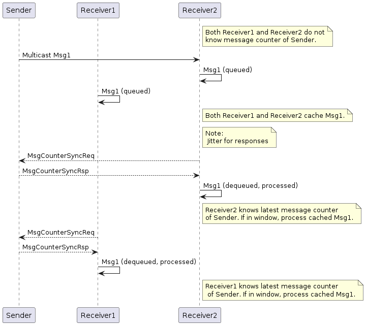
Figure 21. Multicast Receiver Initiated Message Counter Synchronization
Sequence:
• Sender:
    ◦ Generates, encrypts and sends Msg1 as a multicast message. Msg1 could be:
        ▪ Regular message that starts encrypted group communication
            with receivers Receiver1 and Receiver2.

• Receivers Receiver1 and Receiver2 each:
    ◦ Receive, decrypt, authenticate, and cache Msg1 message for later processing.
        ▪ Generate, encrypt, and send `MsgCounterSyncReq` message.

• Sender:
    ◦ Receives `MsgCounterSyncReq` message.
    ◦ Generates, encrypts and sends `MsgCounterSyncRsp` message.

• R1 and R2 each:
    ◦ Receive, decrypt, process, and verify `MsgCounterSyncRsp` message from Sender.
    ◦ On verification success: marks Sender's `group key message counter` as synchronized.
        ▪ Processes cached Msg1 message.
4.17. Bluetooth Transport Protocol (BTP)
The Bluetooth Transport Protocol (BTP) provides a TCP-like layer of reliable, connection-oriented data transfer on top of GATT.
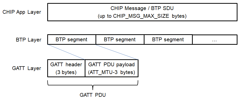
Figure 22. MATTERoBLE(Matter-over-Bluetooth Low Energy): Matter Message / BTP layering
4.17.1. BTP Session Interface
Conceptually, an open BTP session is exposed to the next-higher session layer as a full-duplex message stream.
4.17.2. BTP Frame Formats
A BTP Frame consists of an 8-bit header followed by one or more optional fields
4.17.2.1. BTP Packet Protocol Data Unit
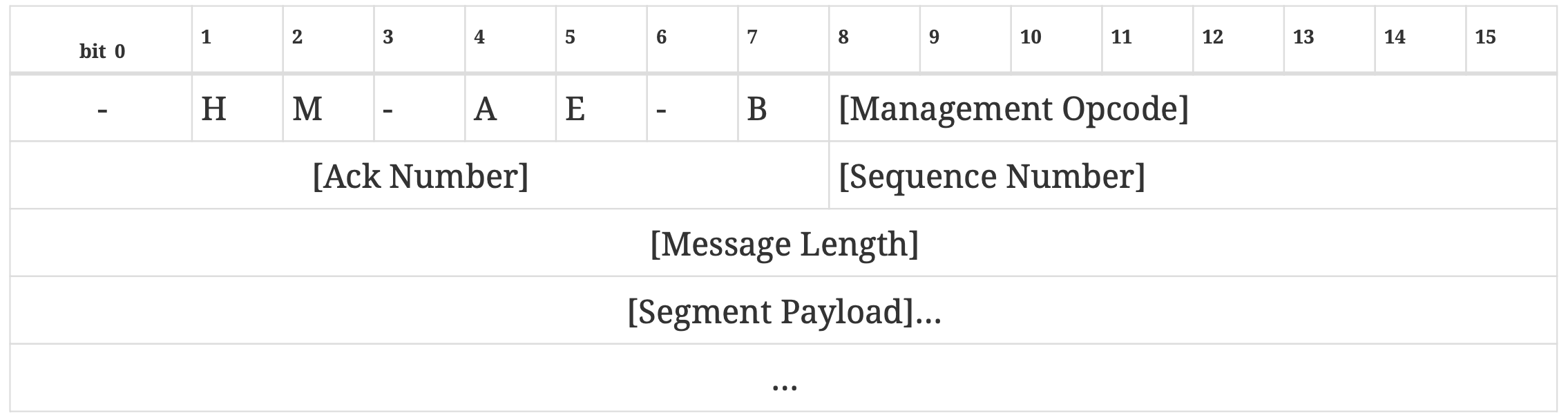
Table 26. BTP Packet PDU format
BTP Packet Protocol Data Unit:
1. H (Handshake) bit
2. M (Management Message) bit
3. A (Acknowledgement) bit
4. B (Beginning Segment) bit
5. E (Ending Segment) bit

a. Ack Number
b. Sequence Number
c. Message Length
d. Segment Payload
4.17.2.2. BTP Control Frames
BTP defines different control frame formats depending on the Management Opcode that is in the BTP Packet PDU header

Table 27. BTP Control codes
4.17.2.3. BTP Handshake Request
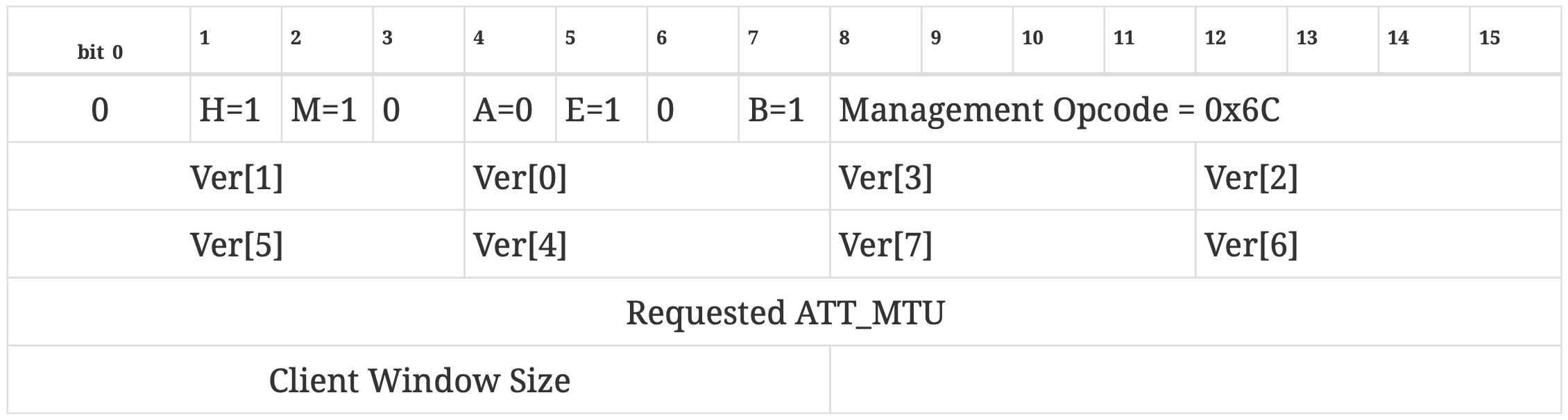
Table 28. BTP Handshake Request format
4.17.2.4. BTP Handshake Response
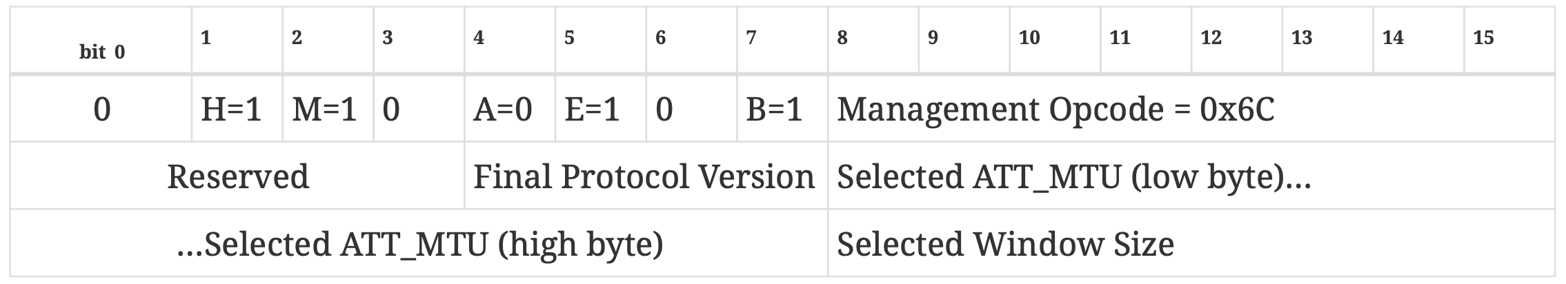
Table 29. BTP Handshake Response format
4.17.3. BTP GATT Service
4.17.3.1. BTP Channelization
Bluetooth Transport Protocol provides a packetized stream interface over GATT but says nothing about the actual contents of the data packets it transports.
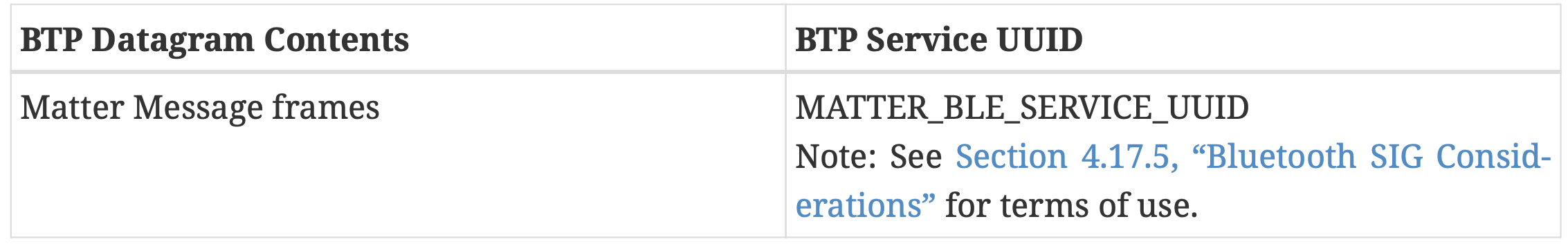
Table 30. BTP Service UUID
4.17.3.2. BTP GATT Service
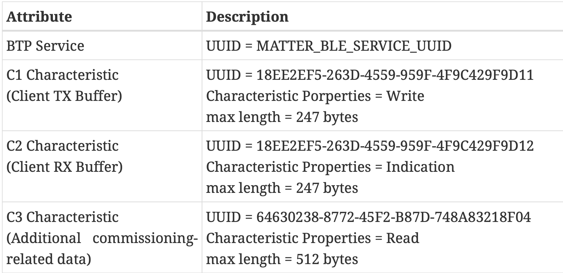
Table 31. BTP GATT service
The BTP GATT service is composed of a service with three characteristics—C1, C2 and C3
4.17.3.3. Session Establishment
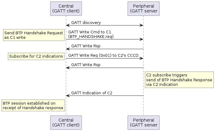
Figure 23. BTP session handshake
4.17.3.4. Data Transmission
Once a BTP session has been established, the next-higher-layer application on both peers may use this BLE connection to send and receive data via GATT
writesorindications, according to a peer’s GATT role.Clients SHALL exclusively use GATT
WriteCharacteristic Value sub-procedure to send data to servers and servers SHALL exclusively use GATTIndicationsub-procedure to send data to clients.
4.17.3.5. Message Segmentation and Reassembly
When the session layer (that is, MATTERoBLE) sends a Matter Message as a
BTP SDUover a BTP session, thatBTP SDUSHALL be split into ordered, non-overlapping BTP segments so the set of all BTP segments may be reassembled into the original BTP SDU(seeFigure 22, “MATTERoBLE: Matter Message / BTP layering”).
4.17.3.6. Sequence Numbers
All BTP packets SHALL be sent with sequence numbers, regardless of whether they contain SDU segments
4.17.3.7. Receive Windows
The purpose of the receive window is to enable flow control at the GATT session layer between BTP peers.
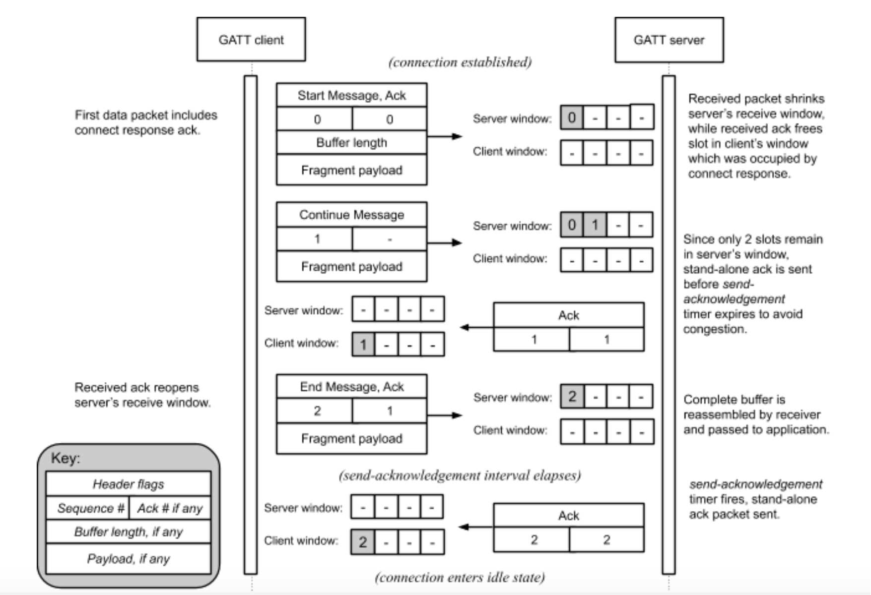
Figure 24. Example receive window scenario
4.17.3.8. Packet Acknowledgements
The purpose of sequence numbers and packet receipt acknowledgements is to support the BTP receive window and provide a keep-alive signal when a session is idle to affirm the health and continued operation of a remote BTP stack.
4.17.3.9. Idle Connection State
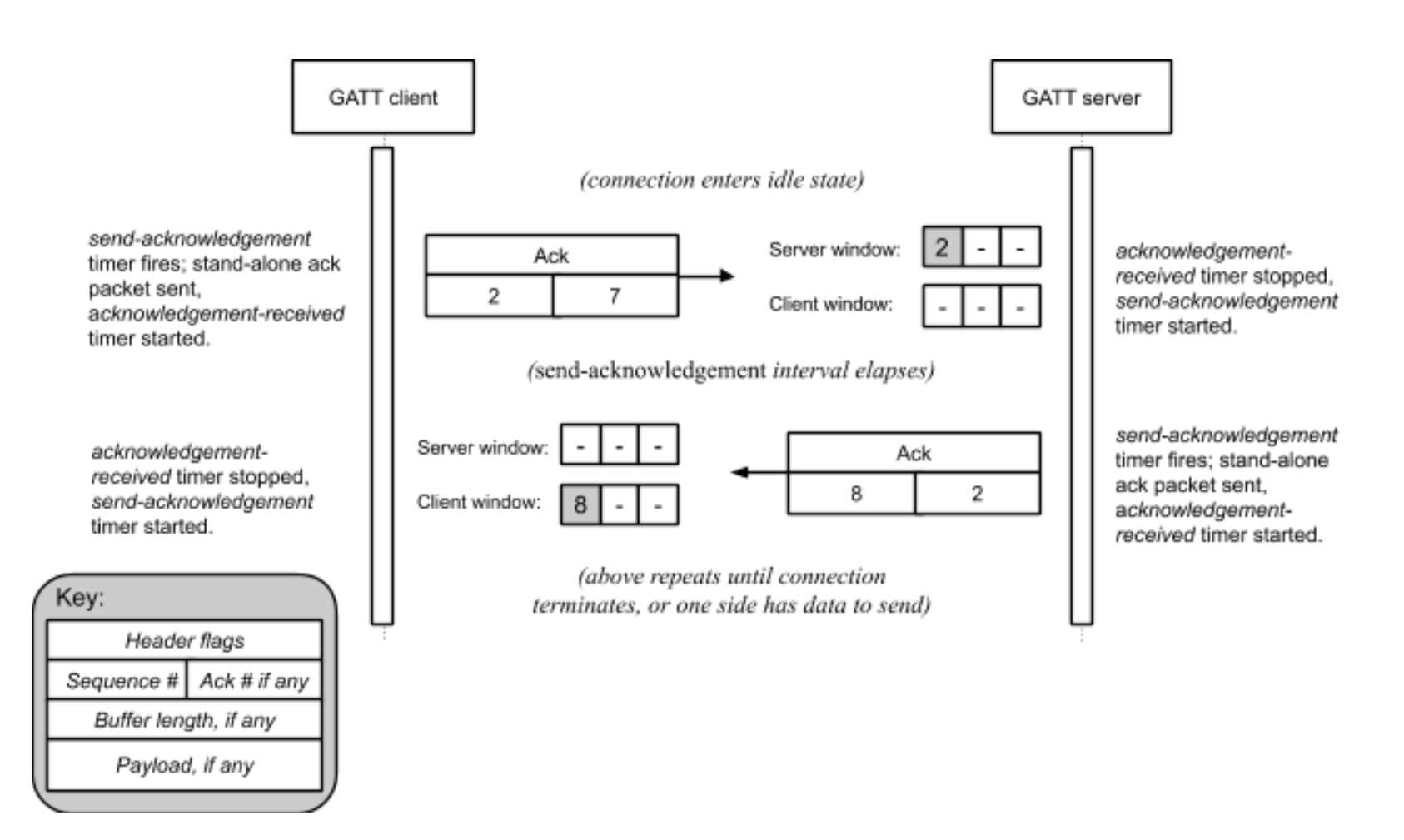
Figure 25. Idle connection scenario
4.17.3.10. Connection Shutdown
To close a BTP session, a GATT client SHALL unsubscribe from characteristic C2. The GATT server SHALL take this action to indicate closure of any BTP session open to the client.
4.17.3.11. Protocol State Diagrams
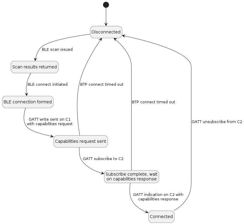
Figure 26. BTP session lifecycle for Central acting as GATT Client: shows the state machine for BTP session management of a BTP Client Device.
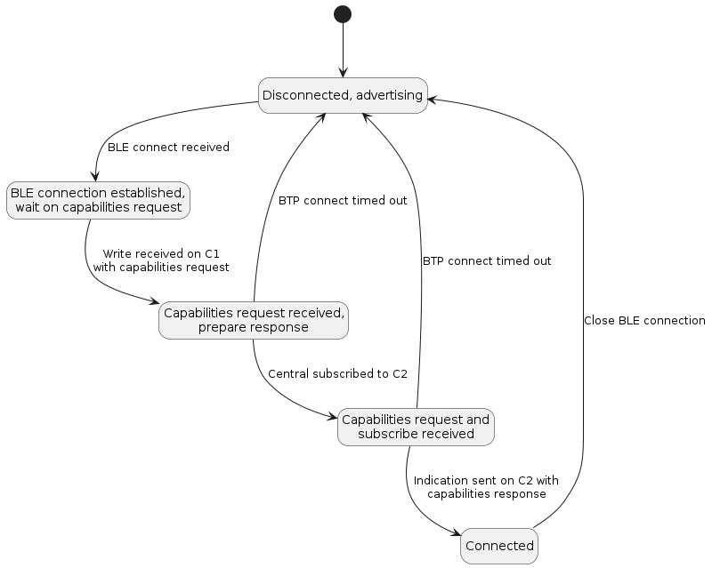
Figure 27. BTP session lifecycle for Peripheral acting as GATT Server: shows the state machine for BTP session management of a BTP Server Device.
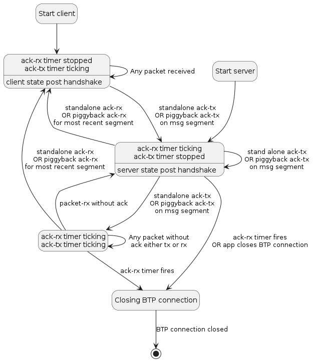
Figure 28. State diagram for BTP session post-establishment: shows the state machine for BTP session maintenance at the protocol level, including liveliness enforcement through keep alive messages and automatic teardown if acknowledgements are received before the timeout.
4.17.4. Parameters and Constants
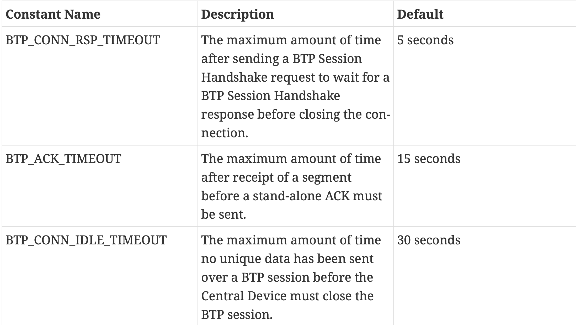
Table 32. Glossary of constants
4.17.5. Bluetooth SIG Considerations
The UUID is provided by Bluetooth SIG, Inc.
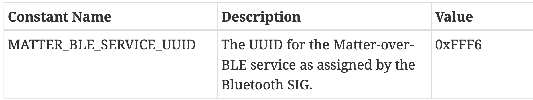
Table 33. SIG UUID assignment
Chapter 5. Commissioning
5.1. Onboarding Payload
The purpose of this section is to define the contents of the Onboarding Payload needed to allow onboarding a device into a Matter network.
It also specifies the representation and encoding of said payload as a QR Code, as a manually entered code, and as content in an NFC tag.
5.1.1 Onboarding Payload Contents:
Version
Vendor ID and Product ID
Custom Flow
    A 2-bit unsigned enumeration specifying the Device Commissioning Flow
       0 indicates that no steps are needed
       1 indicates that user interaction with the device
       2 indicates that an interaction with a service provided by the manufacturer is required
          for initial device setup before it is available for commissioning by any Commissioner.
Discovery Capabilities Bitmask
    8-bit capabilities bitmask
Discriminator value
    12-bit unsigned integer
      For machine-readable formats, the full 12-bit Discriminator is used.
      For the Manual Pairing Code, only the upper 4 bits out of the 12-bit Discriminator are used.
    Usage: distinguish between advertising devices, this value SHOULD be different for each individual device.
Passcode
    27-bit unsigned integer
    0x0000001 to 0x5F5E0FE (00000001 to 99999998 in decimal)
TLV Data
    Tag Length Value
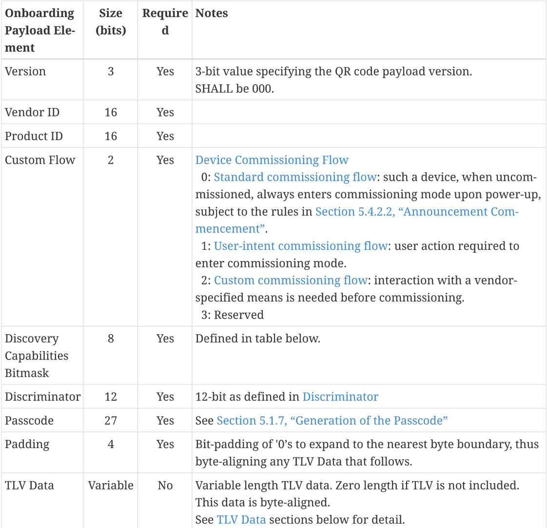
Table 35. Packed Binary Data Structure for Onboarding Payload
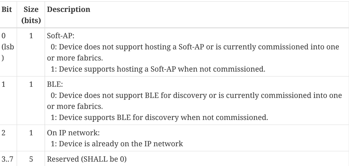
Table 36. Discovery Capabilities Bitmask
5.1.2 Onboarding Material Representation:
Matter Brand Guidelines specify the characteristics like:
  composition, colors, font, font size, QR Code size and digit-grouping of the Manual Pairing code.
5.1.3. QR Code:
QR code string := <prefix><base-38-content>

<prefix>: ``MT:``
<base-38-content>:  (A-Z0-9.-)
5.1.4. Manual Pairing Code:
it SHOULD provide a mechanism such as a copy button to allow easy conveyance
    of the information to other commissioners on the same device.
5.1.5. TLV Content:
A variable-length TLV Data section MAY be encoded into the Packed Binary Data Structure.
The TLV section MAY consist of manufacturer-specific information elements
    and/or elements common to Matter, encoded using TLV.
5.1.6. Concatenation:
MAY be concatenated with additional Onboarding Payloads to be placed in a single QR Code:
QR code string := MT:<onboarding-base-38-content>*<onboarding-base-38-content2>
5.1.7. Generation of the Passcode:
support either dynamic or static passcodes for purposes of establishing the shared secret
    for the initial secure channel over which further onboarding steps take place.
5.1.8. NFC Tag:
The data contained in the NFC tag SHALL be the same as specified in QR Code Format.
5.2. Initiating Commissioning
Commissioner Setup Code Entry, Not Yet Commissioned Device->Launch Commissioner, Enter Code:
1. User initiates an interaction with a Commissioner.
2. User inputs the onboarding payload from the Commissionee.
3. Commissioner determines which technologies to use for Device Discovery.
    IP-bearing networks:
      Commissionable Node Discovery method
      DNS-SD service subtypes for long or short discriminator
      Commissioning mode are specified to filter the results to Commissionees
          match the discriminator in the onboarding payload
          in Commissioning Mode
    BLE or Soft-AP advertisements:
      the discriminator will typically be used to filter the results.
4. Commissioner begins the Commissioning process
User-Initiated Beacon Detection, Not Yet Commissioned Device->Launch Commissioner, Discover New Devices:
1. User initiates an interaction with a Commissioner.
2. User indicates an intention to commission devices without providing additional information about them.
3. Commissioner determines which technologies to use for Device Discovery.
4. Commissioner constructs a list of Commissionees discovered
    VID, PID
    ProductName, ProductLabel
    UserManualUrl, SupportUrl, and ProductUrl
5. User selects Commissionee from list.
6. Commissioner instructs the user to locate and input the onboarding payload.
7. Commissioner begins the Commissioning process
User-Initiated Beacon Detection, Already Commissioned Device->Launch Commissioner, Discover My devices:
1. User initiates an interaction with a Commissioner.
2. User indicates an intention to commission existing devices on the IP network
        without providing additional information about them.
3. Commissioner sends the Commissionable Node Discovery broadcast message.
4. Commissioner constructs a list of Commissionees discovered
5. User selects Commissionee from list.
6. DNS-SD TXT record(includes key/value pairs)can help the Commissioner
    to guide the user through the next steps of the commissioning process.
7. If not already in Commissioning Mode,
    Commissioner instructs the user to put the Commissionee into Commissioning Mode
8. Commissioner instructs the user to locate and input the onboarding payload.
9. Commissioner begins the Commissioning process
Commissioner Discovery, from an On-Network Device->Launch Device UserInterface, Discover Commissioners:
Use case for a Device already on the IP network( TV or Thermostat)
1. User initiates an interaction with the Device.
2. User indicates a desire to connect this Device with a Commissioner on the network.
3. Device uses Commissioner Discovery over DNS-SD on the IP bearing network.
4. Device collects candidates from DNS-SD service records found.
5. Device displays list of Commissioners discovered
6. User selects an entry from the list.
7. Device enters Commissioning Mode.
8. Device displays onboarding payload to the user.
9. Device initiates a User Directed Commissioning session with the selected Commissioner,
    which includes in the DNS-SD service name of the Device.
10. Commissioner prompts user to confirm intention to commission this device
    and asks for onboarding payload.
11. User enters onboarding payload into Commissioner UX.
12. Commissioner begins the commissioning process
5.3. User Directed Commissioning
5.3.1. Overview
The Commissionee sends a message to the Commissioner in order to initiate the commissioning process(see Section 5.5, “Commissioning Flows”).
One possible user journey for this feature is described in
Commissioner Discovery from an Existing Device.
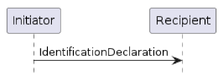
Figure 29. Overview of the UDC Protocol(The Commissionee is the Initiator and the Commissioner is the Recipient.)
5.3.2. UDC Protocol Messages
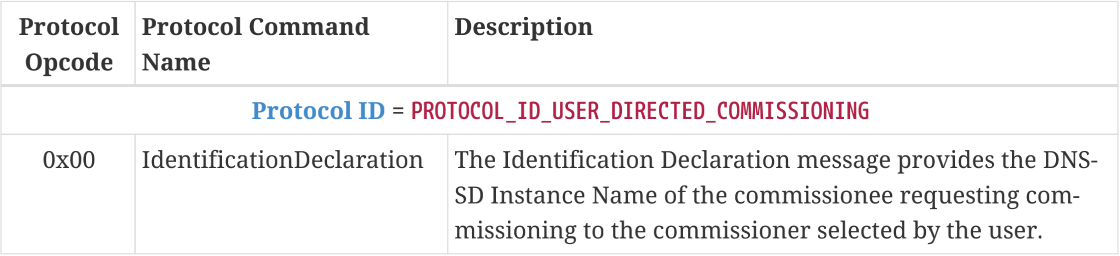
Table 43. User Directed Commissioning Protocol
5.3.3. Message format
All UDC messages are unsecured at the message layer:
• The Session ID field SHALL be set to 0.
• The Session Type bits of the Security Flags SHALL be set to 0.
• The S Flag and DSIZ fields of the Message Flags SHALL be set to 0.
The R Flag of the Exchange Flags for the UDC messages SHALL be set to 0.
For each UDC message, the application payload is the TLV encoding of the message structure as defined below:

Table 44. UDC Messages
5.3.4. Message Exchanges
The I Flag of the Exchange Flags for the UDC messages SHALL be set to 1.
The Initiator MAY send up to 4 retries.
Each retransmission SHALL be delayed by at least 100ms from the previous transmission.
The other fields of the Protocol Header are not specific to the UDC messages.
5.4. Device Discovery
5.4.1. Purpose and Scope:
describe the process by which a device is discovered
    in order to commission it onto an operational Fabric.

1. BLE commissioning
    Generic Access Profile (GAP) for discovery and for connection establishment
    Generic Attribute Profile (GATT) for credential conveyance.
2. Wi-Fi commissioning
    Soft-AP functionality where the device acts as an Access Point (AP)
        that doesn’t provide Internet connectivity.
3. Over IP if a device is already on an IP network
    discover such a device using DNS-based Service Discovery (DNS-SD),
        conveying credentials to the device over IP.
5.4.2. Announcement by Device:
how devices announce their commissionable status
    to allow a Commissioner to discover the device to be commissioned.

1. Technology Priority
    announce in any order of priority on all of the networking technologies(Soft-AP, BLE, IP network)
2. Announcement Commencement
    A device which is not yet commissioned into a Matter fabric SHALL
        commence announcing its ability to be commissioned depending on
        its primary device function and manufacturer-chosen Device Commissioning Flow, per the following table.
    Nodes already commissioned into one or more Matter fabrics and wishing to announce SHALL ONLY
        do so using DNS-SD over their operational network
    In the interest of privacy, an already-commissioned Node SHALL NOT commence announcement
        using Bluetooth LE or Wi-Fi Soft-AP technologies.
3. Announcement Duration
    In order to minimize unnecessary pollution of the crowded 2.4 GHz wireless spectrum
        device SHALL NOT announce for a duration longer than 15 minutes after announcement commences.
    To help strike a balance between a good setup experience and conserving battery life
        device SHALL NOT announce for a duration of less than 3 minutes after announcement commences.
    Note:
        A failed attempt to commission does not restart or delay the timeout.
        Moreover, this timeout applies only to cessation of announcements and not to abortion of connections
4. Discovery Information
    Discriminator: 12-bit
    Vendor ID: 16-bit
    Product ID: 16-bit
    Extended Data: Variable
5. Using BLE
6. Using Wi-Fi Temporary Access Points (Soft-AP)
7. Using Existing IP-bearing Network
5.4.3. Discovery by Commissioner:
1. Using BLE
2. Using Wi-Fi
3. Using Existing IP-bearing Network
5.5. Commissioning Flows
concurrent connection commissioning flow
non-concurrent connection commissioning flow
One connection is between the Commissioner (or Commissionee) and the operational network (e.g., home Wi-Fi network or Thread network) that the Commissionee is being programmed to join.
The second connection is between the Commissioner and Commissionee for commissioning as is referred to as
commissioning channel.A Commissioner and Commissionee with non-concurrent connection capability cannot be simultaneously connected to both the
operational networkthat the Commissionee is being configured to join, and thecommissioning channel.In order to avoid locking out the Commissionee from accepting new PASE session requests indefinitely, a Commissionee SHALL expect a PASE session to be established within 60 seconds of receiving the initial request.
The Commissioner initiating the commissioning SHALL have regulatory and fabric information available, and SHOULD have accurate date, time and timezone.
Commissioner and Commissionee SHALL find each other over networking interfaces such as Bluetooth, Wi-Fi, or Ethernet using the process of discovery and establish a commissioning channel between each other
Commissioner and Commissionee SHALL establish encryption keys with PASE on the commissioning channel.
Commissioner SHALL re-arm the Fail-safe timer on the Commissionee to the desired commissioning timeout within 60 seconds of the completion of PASE session establishment, using the ArmFailSafe command
Commissioner SHALL configure regulatory information in the Commissionee if it has at least one instance of Network Commissioning cluster on any endpoint with either the WI (i.e. Wi-Fi) or TH (i.e. Thread) feature flags set in its FeatureMap.
Commissioner SHALL establish the authenticity of the Commissionee as a certified Matter device
Following the Device Attestation Procedure yielding a decision to proceed with commissioning, the Commissioner SHALL request operational CSR from Commissionee using the CSRRequest command. The CSRRequest command will cause the generation of a new operational key pair at the Commissionee.
Commissioner SHALL generate or otherwise obtain an Operational Certificate containing Operational ID after receiving the CSRResponse command from the Commissionee (see Section 11.17.7.5, “CSRRequest Command”), using implementation-specific means.
Commissioner SHALL install operational credentials (see Figure 38, “Node Operational Credentials flow”) on the Commissionee using the AddTrustedRootCertificate and AddNOC commands.
Commissioner MAY configure the Access Control List on the Commissionee in any way it sees fit, if the singular entry added by the AddNOC command in the previous step, granting Administer privilege over CASE authentication type for the Node ID provided with the command, is not sufficient to express its desired access control policies.
If the Commissionee both supports it and requires it, the Commissioner SHALL configure the operational network at the Commissionee using commands such as AddOrUpdateWiFiNetwork and AddOrUpdateThreadNetwork. A Commissionee requires network commissioning if it is not already on the desired operational network. A Commissionee supports network commissioning if it has any NetworkCommissioning cluster instances. A Commissioner MAY learn about the networks visible to the Commissionee using ScanNetworks command (see Section 11.8.8.2, “ScanNetworks Command”).
The Commissioner SHALL trigger the Commissionee to connect to the operational network using ConnectNetwork command (see Section 11.8.8.10, “ConnectNetwork Command”) unless the Commissionee is already on the desired operational network.
Finalization of the Commissioning process begins. An Administrator configured in the ACL of the Commissionee by the Commissioner SHALL use Operational Discovery to discover the Commissionee. This Administrator MAY be the Commissioner itself, or another Node to which the Commissioner has delegated the task.
The Administrator SHALL open a CASE session with the Commissionee over the operational network.
The Administrator having established a CASE session with the Commissionee over the operational network in the previous steps SHALL invoke the CommissioningComplete command (see Section 11.9.7.6, “CommissioningComplete Command”). A success response after invocation of the CommissioningComplete command ends the commissioning process.
5.5.1. Commissioning Flows Error Handling
In both concurrent/non-concurrent connection commissioning flow, the Commissionee SHALL exit Commissioning Mode after 20 failed attempts.
In both concurrent/non-concurrent connection commissioning flow, the failure of any of the steps 2 through 10 SHALL result in the Commissioner and Commissionee returning to step 2 (device discovery and commissioning channel establishment) and repeating each step.
In concurrent connection commissioning flow, the failure of any of the steps 11 through 15 in concurrent connection commissioning flow SHALL result in the Commissioner and Commissionee returning to step 11 (configuration of operational network information). the Commissioner and Commissionee SHALL reuse the existing PASE-derived encryption keys over the commissioning channel and all steps up to and including step 10 are considered to have been successfully completed.
Once a Commissionee has been successfully commissioned by a Commissioner into its fabric, the commissioned Node SHALL NOT accept any more PASE requests until any one of the following conditions is met: (1)• Device is factory-reset. (2)• Device enters commissioning mode.
5.5.2. Commissioning Flow Diagrams
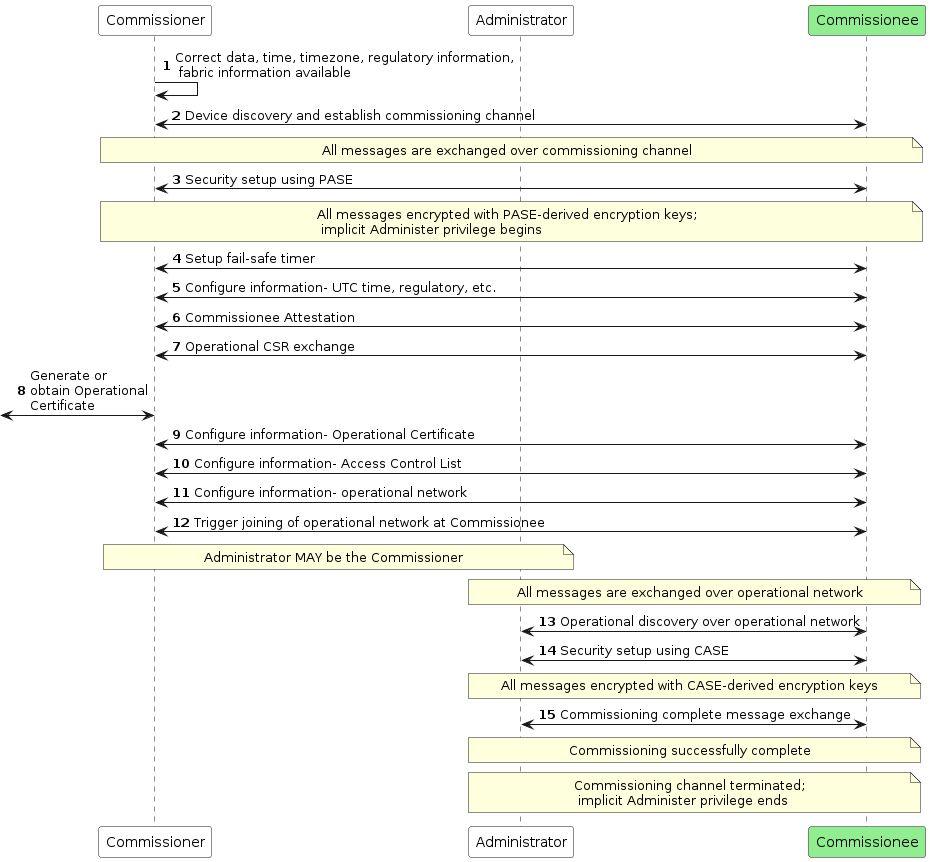
Figure 30. Concurrent connection commissioning flow
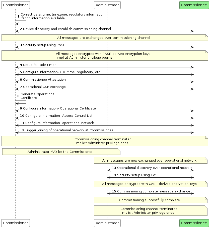
Figure 31. Non-concurrent connection commissioning flow
5.6. Administrator Assisted Commissioning Flows
5.6.1. Introduction
a current Administrator of a Node first sends the Open Commissioning Window command to the Node over a CASE session.
The new Administrator MUST already have network connectivity and complete commissioning based on the two flows described below.
5.6.2. Basic Commissioning Method (BCM)
OPTIONAL
Current Administrator puts the Node in Open Basic Commissioning Window for a specified time window, and receives success response from the Node on the Open Basic Commissioning Window command.
New Administrator completes commissioning within the prescribed window using steps outlined in Figure 30, “Concurrent connection commissioning flow”.
5.6.3. Enhanced Commissioning Method (ECM)
MANDATORY
Current Administrator puts the Node(s) in commissioning mode for a specified time window with a new setup passcode, and receives success responses from the involved Node(s) on the Open Commissioning Window command.
Current Administrator presents Onboarding Payload
New Administrator completes commissioning within the prescribed window using steps outlined in Figure 30, “Concurrent connection commissioning flow”.
5.6.4. Open Commissioning Window
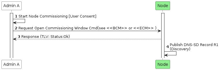
Steps current Administrator takes to enable Open Commissioning Window.
5.7. Device Commissioning Flows
The three flows are the following:
• Standard Commissioning Flow
• User-Intent Commissioning Flow
• Custom Commissioning Flow
备注
Custom Commissioning Flow是一些定制化的东西。
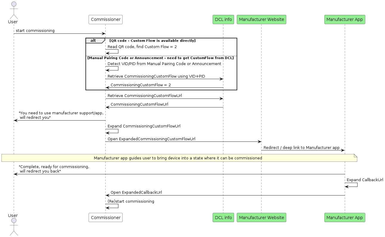
Figure 33. Custom Commissioning Flow sequence diagram
5.8. In-field Upgrade to Matter
pre-Matter device currently in the user’s home which gets software updated to support Matter
Chapter 6. Device Attestation and Operational Credentials
This chapter describes the procedures and cryptographic credentials involved in establishing trust between entities.
The
Device Attestationsection provides mechanisms for Commissioners and Administrators to determine whether a Node is a genuine certified product before sharing sensitive information such as keys and other credentials. TheDevice Attestationfeature relies on aDevice Attestation Certificate (DAC) chainand on aCertification Declaration (CD).The
Node Operational Credentialssection describes the credentials used by all Nodes to mutually authenticate each other duringCertificate-Authenticated Session Establishment, including theNode Operational Certificate (NOC) chain. These credentials form the basis of how Nodes are identified and take part in securing operational unicast communication.
6.1. Common Conventions
This chapter makes use of digital certificates in several subsections.
The storage format of the certificates depends on application (e.g., DAC or NOC chain), but all certificates are directly compatible with X.509v3 DER representation after suitable loading or decompression.
The following certificate formats are defined within this specification:
• Compressed `Node Operational credentials` certificate chain elements
    in `Matter Operational Certificate Encoding` or "Matter Certificate" format:
    ◦ Node Operational Certificate (NOC)
    ◦ Intermediate CA Certificate (ICAC)
    ◦ Root CA Certificate (RCAC)

• Device Attestation certificate chain elements
    in Standard X.509 DER format:
    ◦ Device Attestation Certificate (DAC)
    ◦ Product Attestation Intermediate (PAI)
    ◦ Product Attestation Authority (PAA)
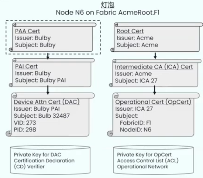
示例
6.1.1. Encoding of Matter-specific RDNs
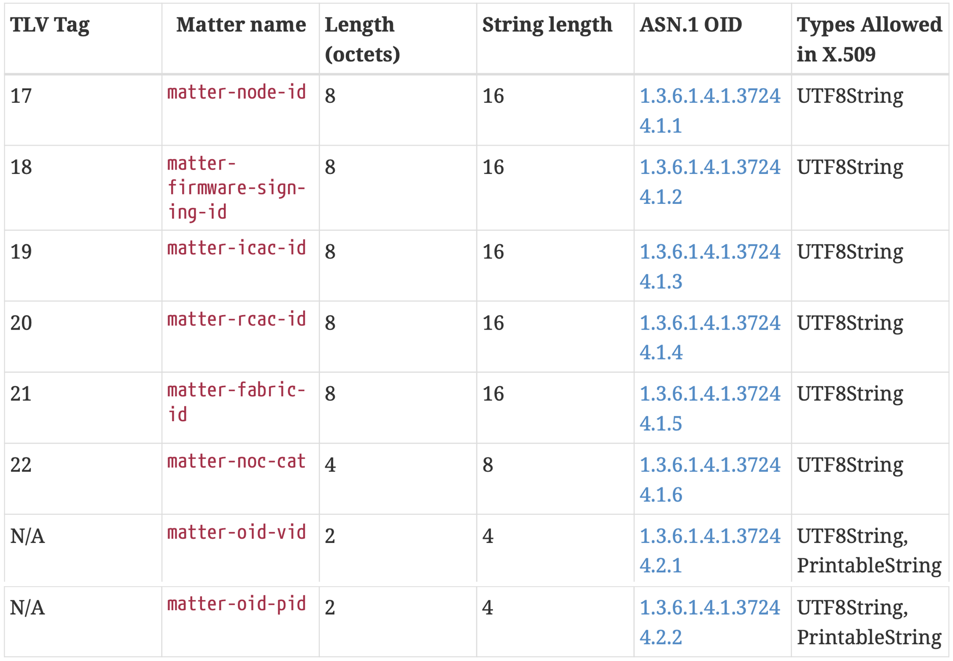
Table 54. Matter-specific DN Object Identifiers
A scalar value 0x0123_4567_89AB_CDEF for matter-node-id:
◦ Scalar maximal length: 8 octets (64 bits)
◦ Resulting string: "0123456789ABCDEF" (without quotes)
◦ Resulting length: 16 characters
A scalar value
0xAA_33CCformatter-noc-cat:◦ Scalar maximal length: 4 octets (32 bits) ◦ Resulting string: "00AA33CC" (without quotes) ◦ Resulting length: 8 characters
6.1.2. Key Identifier Extension Constraints
Further constraints related to the exact derivation appear in the following subsections:
• Matter Certificates (NOC, ICAC, RCAC) Subject Key Identifier extension
• Matter Certificates Authority Key Identifier extension
• Device Attestation Certificate (DAC) extensions
• Product Attestation Intermediate (PAI) Certificate extensions
• Product Attestation Authority (PAA) Certificate extensions
6.1.3. Certificate Sizes
All certificates SHALL NOT be longer than 600 bytes in their uncompressed DER format. This constraints SHALL apply to the entire
DAC chain (DAC, PAI, PAA)andNOC chain (NOC, ICAC, RCAC).Wherever
Matter Operational Certificate Encodingrepresentation is used, all certificates SHALL NOT be longer than 400 bytes in their TLV form. This constraint only applies to theNOC chain
6.1.4. Presentation of example certificates
Certificate bodies are presented for exemplary purposes in multiple formats within this chapter.
Since the translation of an X.509 certificate from
ASN.1 DERformat tohuman-readable textformat may lose fidelity, textual examples SHALL NOT be considered to be normative.Only direct encoding of DER encoding, such as PEM blocks, should be used to further study the examples.
6.2. Device Attestation
6.2.1. Introduction
This chapter describes the
Device Attestation Certificate (DAC)and the systems involved in the verification of aDAC.The processes used to convey the DAC from a Commissionee to a Commissioner, how to verify that a Commissionee holds the private key corresponding to its DAC
6.2.2. Device Attestation Certificate (DAC)
The
DACalso SHALL contain specific values ofVendor IDandProduct IDin its subject field to indicate the Vendor ID and Product ID provenance of the attestation certificate.The validity period of a DAC is determined by the vendor and MAY be set to the maximum allowed value of
99991231235959ZGeneralizedTime to indicate that the DAC has no well-defined expiration date.
6.2.2.1. Device Attestation Public Key Infrastructure (PKI)
The Device Attestation PKI hierarchy consists of the PAA, PAI and individual DAC.
A PAI SHALL be assigned to a Vendor ID value. A PAI MAY further be scoped to a single ProductID value.
The subject of all DAC and PAI certificates SHALL be a unique combination of commonName (OID 2.5.4.3), serialNumber (OID 2.5.4.5), organizationalUnitName (OID 2.5.4.11), etc.
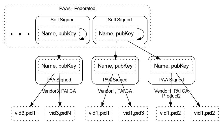
Figure 34. Device Attestation PKI hierarchy
6.2.2.2. Encoding of Vendor ID and Product ID in subject and issuer fields
The values for VendorID and ProductID, where possible or required in issuer or subject fields SHALL be encoded by only one of two methods, without mixing the methods within a given field:
1. The `"preferred method"`, using Matter-specific `RelativeDistinguishedName` attributes:
    a. VendorID encoded as `AttributeTypeAndValue` entry with type equal to 1.3.6.1.4.1.37244.2.1
    b. ProductID encoded as `AttributeTypeAndValue` entry with type equal to 1.3.6.1.4.1.37244.2.2

2. A `"fallback method"`:
    a. VendorID value encoded with substring Mvid:
        i. VendorID 0xFFF1 (65521 decimal): Mvid:FFF1
        ii. VendorID 0x2A (42 decimal): Mvid:002A
    b. ProductID value encoded with substring Mpid:
        i. ProductID 0xC20A (49674 decimal): Mpid:C20A
        ii. ProductID 0x3A5 (933 decimal): Mpid:03A5
The
"preferred method"leaves more space for content in the commonName attribute type if present.The
"fallback method"is present to support less flexible CA infrastructure.
VendorID 0xFFF1 and ProductID 0x00B1 can be illustrated with the following valid and invalid examples:
• "ACME Matter Devel DAC 5CDA9899 Mvid:FFF1 Mpid:00B1": valid and recommended
• "ACME Matter Devel DAC 5CDA9899 Mpid:00B1 Mvid:FFF1": valid and recommended
• "Mpid:00B1,ACME Matter Devel DAC 5CDA9899,Mvid:FFF1": valid
• "ACME Matter Devel DAC 5CDA9899 Mvid:FFF1Mpid:00B1": valid, but less readable
• "Mvid:FFF1ACME Matter Devel DAC 5CDAMpid:00B19899": valid, but highly discouraged
• "ACME Matter Devel DAC 5CDA9899 Mvid:FF1 Mpid:00B1": invalid
• "ACME Matter Devel DAC 5CDA9899 Mvid:fff1 Mpid:00B1": invalid
• "ACME Matter Devel DAC 5CDA9899 Mvid:FFF1 Mpid:B1": invalid
• "ACME Matter Devel DAC 5CDA9899 Mpid: Mvid:FFF1": invalid
If either the
Vendor ID (1.3.6.1.4.1.37244.2.1)orProduct ID (1.3.6.1.4.1.37244.2.2)Matter-specific OIDs appear in anyRelativeDistinguishedNamein thesubjectorissuerfieldsthen that certificate within the chain SHALL NOT have its commonName
6.2.2.3. Device Attestation Certificate (DAC)
TBSCertificate structure:
1. The `version` field SHALL be set to 2 to indicate v3 certificate.
2. The `signature` field SHALL contain the identifier for signatureAlgorithm `ecdsa-with-SHA256`.
3. The `issuer` field SHALL be a sequence of `RelativeDistinguishedName` s.
4. The `issuer` field SHALL have exactly one `VendorID` value present.
5. The `issuer` field SHALL have exactly zero or one `ProductID` value present.
6. The `subject` field SHALL be a sequence of `RelativeDistinguishedName` s.
7. The `subject` field SHALL have exactly one `VendorID` value present.
8. The `subject` field SHALL have exactly one `ProductID` value present.
9. The `algorithm` field in `subjectPublicKeyInfo` field SHALL be the object identifier for `prime256v1`.
0. The certificate SHALL carry the following Extensions:
    a. `Basic Constraint` extension SHALL be marked `critical` and have the cA field set to FALSE.
    b. `Key Usage` extension SHALL be marked `critical`
        i. The KeyUsage bitstring SHALL only have the digitalSignature bit set.
        ii. Other bits SHALL NOT be set
    c. `Authority Key Identifier`
    d. `Subject Key Identifier`
1. The certificate MAY also carry the following additional Extensions:
    a. `Extended Key Usage`
    b. `Authority Information Access`
    c. `Subject Alternate Name`
Human-readable contents of example DAC X.509 certificate:
Certificate:
     Data:
         Version: 3 (0x2)
         Serial Number: 1010560536528535133 (0xe063b742bcfbe5d)
         Signature Algorithm: ecdsa-with-SHA256
         Issuer: CN = Matter Test PAI, 1.3.6.1.4.1.37244.2.1 = FFF1,
 1.3.6.1.4.1.37244.2.2 = 8000
         Validity
             Not Before: Jun 28 14:23:43 2021 GMT
             Not After : Dec 31 23:59:59 9999 GMT
          Subject: CN = Matter Test DAC 0001, 1.3.6.1.4.1.37244.2.1 = FFF1,
 1.3.6.1.4.1.37244.2.2 = 8000
         Subject Public Key Info:
             Public Key Algorithm: id-ecPublicKey
                 Public-Key: (256 bit)
                 pub:
                     04:c2:25:83:22:c7:dc:72:73:7c:33:be:ed:70:73:
                     37:aa:24:85:bc:46:79:3e:4d:5a:c9:a7:5a:d7:43:
                     52:66:c9:0a:02:8e:ec:af:26:50:fe:70:09:ef:fc:
                     ae:cb:ea:d1:f2:c3:d1:24:35:de:c2:ea:d3:d9:92:
                     95:bf:ce:d6:c3
                 ASN1 OID: prime256v1
                 NIST CURVE: P-256
         X509v3 extensions:
             X509v3 Basic Constraints: critical
                 CA:FALSE
             X509v3 Key Usage: critical
                 Digital Signature
             X509v3 Subject Key Identifier:
                 96:C2:D9:24:94:EA:97:85:C0:D1:67:08:E3:88:F1:C0:91:EA:0F:D5
             X509v3 Authority Key Identifier:
                 keyid:AF:42:B7:09:4D:EB:D5:15:EC:6E:CF:33:B8:11:15:22:5F:32:52:88
     Signature Algorithm: ecdsa-with-SHA256
          30:45:02:20:5f:cb:29:a4:0d:3c:35:a6:e8:ce:60:65:c6:d0:
          9d:a6:17:3d:c5:b2:45:ec:32:04:91:e3:d3:49:32:b7:3e:17:
          02:21:00:b4:56:99:0f:52:05:10:04:5a:38:8f:75:4e:77:15:
          40:a0:44:97:92:31:96:45:5e:44:0d:68:25:d9:61:03:64
Human-readable contents of example DAC X.509 certificate, using “fallback method” for VendorID and ProductID in Subject:
Certificate:
      Data:
           Version: 3 (0x2)
          Serial Number: 7919366188737521296 (0x6de73d970df06690)
          Signature Algorithm: ecdsa-with-SHA256
          Issuer: CN = Matter Test PAI, 1.3.6.1.4.1.37244.2.1 = FFF1,
  1.3.6.1.4.1.37244.2.2 = 8000
          Validity
              Not Before: Jun 28 14:23:43 2021 GMT
              Not After : Dec 31 23:59:59 9999 GMT
          Subject: CN = Matter Test DAC 0001 Mvid:FFF1 Mpid:8000
          Subject Public Key Info:
              Public Key Algorithm: id-ecPublicKey
                  Public-Key: (256 bit)
                  pub:
                      04:c2:25:83:22:c7:dc:72:73:7c:33:be:ed:70:73:
                      37:aa:24:85:bc:46:79:3e:4d:5a:c9:a7:5a:d7:43:
                      52:66:c9:0a:02:8e:ec:af:26:50:fe:70:09:ef:fc:
                      ae:cb:ea:d1:f2:c3:d1:24:35:de:c2:ea:d3:d9:92:
                      95:bf:ce:d6:c3
                  ASN1 OID: prime256v1
                  NIST CURVE: P-256
          X509v3 extensions:
              X509v3 Basic Constraints: critical
                  CA:FALSE
              X509v3 Key Usage: critical
                  Digital Signature
              X509v3 Subject Key Identifier:
                  96:C2:D9:24:94:EA:97:85:C0:D1:67:08:E3:88:F1:C0:91:EA:0F:D5
              X509v3 Authority Key Identifier:
                  keyid:AF:42:B7:09:4D:EB:D5:15:EC:6E:CF:33:B8:11:15:22:5F:32:52:88
      Signature Algorithm: ecdsa-with-SHA256
           30:44:02:20:6e:f6:2c:1d:a1:91:4e:0d:49:cc:f4:c1:e9:3a:
           9f:54:53:c0:04:5f:0b:09:89:04:3f:50:2f:57:b0:21:c8:be:
           02:20:00:8a:5b:70:3a:62:2c:6a:b6:a2:9f:93:0b:af:c3:cd:
           66:31:5c:a6:a9:a7:d4:f2:4c:79:93:57:34:ce:a6:de
6.2.2.4. Product Attestation Intermediate (PAI) Certificate
TBSCertificate structure:
1. The ``version`` field SHALL be set to 2 to indicate v3 certificate.
2. The ``signature`` field SHALL contain the identifier for signatureAlgorithm ``ecdsa-with-SHA256``
3. The ``issuer`` field SHALL be a sequence of ``RelativeDistinguishedName`` s.
4. The ``issuer`` field SHALL have exactly zero or one VendorID value present.
5. The ``subject`` field SHALL be a sequence of ``RelativeDistinguishedName`` s.
6. The ``subject`` field SHALL have exactly one ``VendorID`` value present.
7. The ``subject`` field SHALL have exactly zero or one ``ProductID`` value present.
8. The ``algorithm`` field in subjectPublicKeyInfo field SHALL be the object identifier for ``prime256v1``.
9. The ``certificate`` SHALL carry the following Extensions:
    a. ``Basic Constraint`` extension SHALL be marked `critical`
        and have the cA field set to TRUE and pathLen field set to 0.
    b. `Key Usage` extension SHALL be marked `critical`
    c. Authority Key Identifier
    d. Subject Key Identifier
0. The certificate MAY also carry the following additional Extensions:
    a. Extended Key Usage
6.2.3. Device Attestation Procedure
The device attestation procedure SHALL be executed by Commissioners when commissioning a device.
It serves to validate whether a particular device is certified for Matter compliance and that it was legitimately produced by the certified manufacturer.
Commissioner SHALL request the Commissionee’s Device Attestation Certificate Chain as follows:
1. The Commissioner SHALL generate a random 32 byte attestation nonce using Crypto_DRBG().
2. The Commissioner SHALL send the `AttestationNonce` to the Commissionee
    and request Attestation Information using Section 11.17.7.1, “AttestationRequest Command”.
3. The Commissionee SHALL return the signed Attestation Information to the Commissioner
6.2.3.1. Attestation Information Validation
A Commissioner validating the Attestation Information SHOULD record sufficient information to provide detailed results of the validation outcome to users.
In order to consider a Commissionee successfully attested, a Commissioner SHALL have successfully validated at least the following:
1. The `PAA` SHALL be validated for presence in the Commissioner’s trusted root store
2. The `DAC` certificate chain SHALL be validated using the Crypto_VerifyChainDER() function,
    taking into account the mandatory presence of the PAI and of the PAA.
3. The `VendorID` value found in the subject DN of the DAC
    SHALL match the VendorID value in the subject DN of the PAI certificate.
4. If the `PAA` certificate contains a VendorID value in its subject DN,
    its value SHALL match the VendorID value in the subject DN of the PAI certificate.
5. The Device Attestation Signature (`attestation_signature`) field from Attestation Response
    SHALL be validated
6. The `AttestationNonce` in Device Attestation elements
    SHALL match the Commissioner’s provided AttestationNonce.
7. The `Certification Declaration signature`
    SHALL be validated using the Crypto_Verify() function and the public key
    obtained from the CSA’s Certificate Authority Certificate.
8. The Certification Declaration SHALL be validated
6.3. Certification Declaration
A Certification Declaration (CD) is a cryptographic document that allows a Matter device to assert its protocol compliance.
It is encoded in a CMS format described in
RFC 5652.
6.3.1. Certification Declaration (CD) Format
The Certification Declaration is a CMS-encoded single-signature envelope whose message is a TLV-encoded certification-elements structure with an anonymous tag:
Certification Elements TLV structure:
certification-elements => STRUCTURE [ tag-order ]
{
    format_version [0]          : UNSIGNED INTEGER [ range 16-bits ]
    vendor_id [1]               : UNSIGNED INTEGER [ range 16-bits ]
    product_id_array [2]        : ARRAY [ length 1..100 ] OF UNSIGNED INTEGER [ range 16-bits ]
    device_type_id [3]          : UNSIGNED INTEGER [ range 32-bits ]
    certificate_id [4]          : STRING [length 19]
    security_level [5]          : UNSIGNED INTEGER [ range 32-bits ]
    security_information [6]    : UNSIGNED INTEGER [ range 16-bits ]
    version_number [7]          : UNSIGNED INTEGER [ range 16-bits ]
    certification_type [8]      : UNSIGNED INTEGER [ range 8-bits]
    dac_origin_vendor_id [9, optional]   : UNSIGNED INTEGER [ range 16-bits ]
    dac_origin_product_id [10, optional] : UNSIGNED INTEGER [ range 16-bits ]
    authorized_paa_list [11, optional]   : ARRAY [ length 1..10 ] OF OCTET STRING [ length 20 ]
}
The Certification Elements TLV is encoded with data to form a cd_content message to be signed:
cd_content =
{
    format_version (0)            = 1,
    vendor_id (1)                 = <vendor_id>,
    product_id_array (2)          = <array of product_id values>,
    device_type_id (3)            = <primary device type identifier>,
    certificate_id (4)            = <globally unique certificate ID issued by CSA>,
    security_level (5)            = 0,
    security_information (6)      = 0,
    version_number (7)            = <version_number>,
    certification_type (8)        = <certification_type>,
    dac_origin_vendor_id (9)      = <Vendor ID associated with the DAC, optional>,
    dac_origin_product_id (10)    = <Product ID associated with the DAC, optional>,
    authorized_paa_list (11)      = <array of PAA SKIs, optional>
}
The certification_type field SHALL contain the type of certification for this CD:
0:
    used for development and test purposes
1:
    provisional - used for a device when going into certification testing,
    or to allow production and distribution to occur in parallel with certification
    (with potential software fixes yielding a higher SoftwareVersion which gets certification)
2:
    official - allocated after passing certification
other values:
    reserved
Certification Declaration CMS ASN.1 Encoding Format:
CertificationDeclaration ::= SEQUENCE {
    version             INTEGER ( v3(3) ),
    digestAlgorithm     OBJECT IDENTIFIER `sha256` (2.16.840.1.101.3.4.2.1),
    encapContentInfo    EncapsulatedContentInfo,
    signerInfo          SignerInfo
}

EncapsulatedContentInfo ::= SEQUENCE {
    eContentType    OBJECT IDENTIFIER `pkcs7-data` (1.2.840.113549.1.7.1),
    eContent        OCTET STRING cd_content
}

SignerInfo ::= SEQUENCE {
    version                 INTEGER ( v3(3) ),
    subjectKeyIdentifier    OCTET STRING,
    digestAlgorithm         OBJECT IDENTIFIER `sha256` (2.16.840.1.101.3.4.2.1),
    signatureAlgorithm      OBJECT IDENTIFIER `ecdsa-with-SHA256` (1.2.840.10045.4.3.2),
    signature               OCTET STRING
}
备注
Note that Certification Declarations SHALL NOT be generated by any Node, but rather, they SHALL be stored and transmitted to a Commissioner by a Commissionee during the conveyance of the Attestation Information in response to an Attestation Request command.
6.3.2. Firmware Information
Firmware Information is an optional component of the
Device Attestation InformationFirmware Information MAY contain one or more Firmware Digests that correspond to the components in the firmware that have been measured and recorded during the boot process (e.g., bootloader, kernel, root filesystem, etc), and MAY contain other metadata.
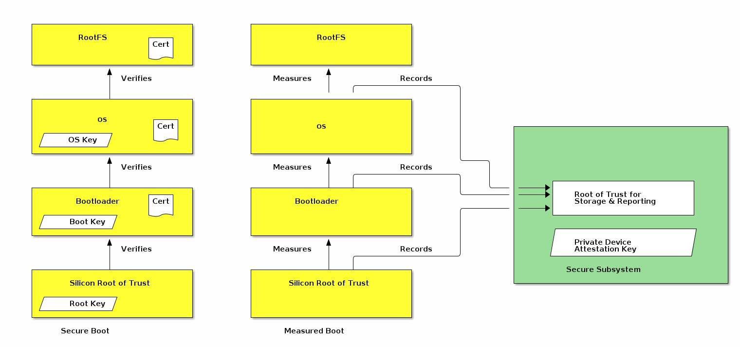
Figure 35. Illustration of the measured boot process
6.3.3. Firmware information validation examples
Below is an illustrative example of the Commissioner actions to validate the firmware information:
1. Retrieve the `firmware_information` field from `attestation-elements`
2. Retrieve all `Distributed Compliance Ledger DeviceSoftwareVersionModel` entries
    for the Commissionee’s Vendor ID and Product ID.
3. Verify that there is a valid, non-revoked, entry
    where the `FirmwareInformation` field exactly matches
    the `firmware_information` field in attestation-elements.
4. If verification fails, report error to the user
5. If verification succeeds, proceed with device commissioning
Below is an example of the corresponding Device actions:
1. The device bootloader produces a measurement of the OS kernel
    using a supported hash algorithm from `RFC 5912` and delivers it to the secure subsystem.
2. The secure subsystem receives the measurement and stores in a location inaccessible to the OS.
3. The OS kernel produces a hash of the root filesystem and delivers the measurement to the secure subsystem.
4. When the secure subsystem is asked to sign an attestation-elements structure
    using its private device attestation key,
    it generates two FirmwareDigests or one combined FirmwareDigest from these measurements,
    fills the firmware_information field in attestation-elements using these measurements,
    fills the CD blob compiled into the secure environment
    and signs the attestation-elements structure.
6.4. Node Operational Credentials Specification
6.4.1. Introduction
The Node Operational credentials are a collection of credentials to enable a Node to identify itself within a Fabric.
The Node Operational credentials are distinct from the Device Attestation credentials. The Node Operational credentials are installed during Commissioning.
The Node Operational credentials include the following items:
• Node Operational Key Pair
• Node Operational Certificate (NOC)
• Intermediate Certificate Authority (ICA) Certificate (optional)
• Trusted Root Certificate Authority (CA) Certificate(s)
6.4.2. Node Operational Credentials Management
Commands from the
Node Operational Credentials Clusterare used to install and update Node Operational credentials.A Node
1. initial through the `AddNOC` command
2. update using the `UpdateNOC` command
3. remove using the `RemoveFabric` command
6.4.3. Node Operational Identifier Composition
The
Node Operational Identifieris used for Node discovery and network address resolution within a network segment.The
FabricIDportion of the Node Operational Identifier serves a scoping purpose to identify disjoint operational Fabrics within a given network segment.The
NodeIDportion of the Node Operational Identifier is the logical addressing identifier used:• within `Message-layer messages` for logical addressing • within `Data Model bindings` to express data subscription relationships between Nodes • within `ACL Entries` to refer to individual Nodes as access control grantees(subjects) when CASE sessions are used for communicationIn addition to the
FabricIDandNodeID, a Node Operational Identifier MAY include at most three 32-bitCASEAuthenticatedTag(1.3.6.1.4.1.37244.1.6) attributes used to tag the operational identifier to implement access control based onCASE Authenticated Tags.
6.4.4. Node Operational Key Pair
A Node Operational Key Pair, comprised of a Node Operational Public Key and a Node Operational Private Key, is created using the Crypto_GenerateKeypair function
6.4.5. Node Operational Credentials Certificates
6.4.5.1. Node Operational Certificate (NOC)
The NOC SHALL be issued by either a Root CA trusted within the Fabric or by an Intermediate Certificate Authority (ICA) whose ICA certificate is directly issued by such a Root CA.
6.4.5.2. Intermediate CA (ICA) Certificate
In the case where an intermediate CA (ICA) issues the NOC, the ICA certificate is used to attest to the validity of the NOC.
6.4.5.3. Trusted Root CA Certificates
Each Node has one or more
trusted Root CA certificatesin itsNode Operational credentialsthat it uses to verifyICA certificatesandNode Operational Certificatespresented by other Nodes, treating them as trust anchors as described in RFC 5280.The certificates configured in that cluster SHALL only be added during the commissioning process by the Commissioner, or during root rotation operations by an Administrator already trusted by the Node.
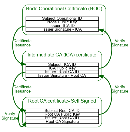
Figure 36. Node Operational Certificate PKI hierarchy with optional ICAC
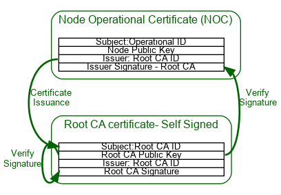
Figure 37. Node Operational Certificate PKI hierarchy without optional ICAC
6.4.6. Node Operational Credentials Procedure
6.4.6.1. Node Operational Certificate Signing Request (NOCSR) Procedure
After the Commissioner validates Device Attestation Information, the following procedure is used to generate a Node Operational Key Pair and obtain the NOCSR:
1. The Commissioner SHALL generate a random 32 byte nonce named `CSRNonce` using Crypto_DRBG().
2. The Commissioner SHALL send the `CSRNonce` to the Node
    and request `NOCSR` Information using the `CSRRequest` Command.
    a. The Node SHALL create a new candidate `Node Operational Key Pair`
    b. The Node SHOULD verify the newly generated candidate `Node Operational Key Pair`
    c. The candidate Node Operational Key Pair SHALL only be committed to persistent storage
    d. The Node SHALL create a Certificate Signing Request (CSR)
    e. The CSR’s subject MAY be any value
        and the device SHOULD NOT expect the final operational certificate
        to contain any of the CSR’s subject DN attributes.
3. The Node SHALL generate and return the `NOCSR` Information to the Commissioner
    using the CSRResponse Command.
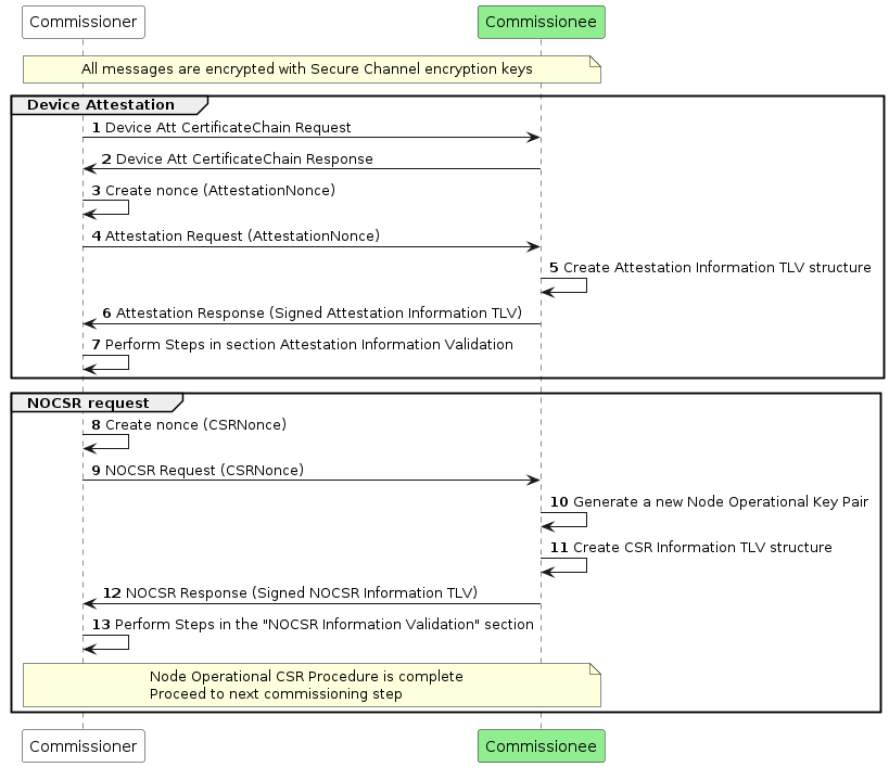
Figure 38. Node Operational Credentials flow
6.4.7. Node Operational Certificate Signing Request (NOCSR)
A Node creates a
NOCSRin response to the Commissioner, so that the Commissioner can request a NOC on the Node’s behalf from its trusted Certificate Authority.
NOCSR:
Certificate Request:
     Data:
         Version: 1 (0x0)
         Subject: ...............
         Subject Public Key Info:
             Public Key Algorithm: id-ecPublicKey
                 Public-Key: (256 bit)
                 pub:
                     04:12:3b:90:f5:.......
                 ASN1 OID: prime256v1
                 NIST CURVE: P-256
         Attributes:
         Requested Extensions:
     Signature Algorithm: ecdsa-with-SHA256
          30:46:02:21:00:95:ff:......
6.4.8. Node Operational Certificate Renewal
A NOC can be renewed by an Administrator.
6.4.9. Node Operational Certificate Revocation
A Node’s access to other Nodes can be revoked by removing the associated Node ID from Access Control Entry subjects where it appears.
6.4.10. Security Considerations
A NOC is a Node’s credential to operate on a Fabric. It SHALL be protected against the following threats:
1. The Node Operational Private Key SHALL be protected from unauthorized access.
2. The Node Operational Private Key SHOULD never leave the device.
3. The NOC SHALL NOT contain information that may violate the user’s privacy.
4. The NOC SHALL be wiped if the Node is factory reset.
6.5. Operational Certificate Encoding
6.5.1. Introduction
This section details the
Matter certificate data structure(hereafter “Matter certificate”), a specific encoding that is sometimes used as a compact alternative to the standard X.509 certificate format [RFC 5280] for bandwidth-efficient transmission.To compress the structure more efficiently than an
X.509 certificate, aMatter certificateSHALL be encoded with theMatter TLV structured data interchange language[Appendix A, Tag-length-value (TLV) Encoding Format] instead of the A``SN.1 Distinguished Encoding Rules (DER)`` [X.690].
A certificate comprises a record of the following conceptual fields:
Certificate Text
      Version Number
      Serial Number
      Signature Algorithm ID
      Issuer Name
      Validity period
          Not Before
          Not After
      Subject name
      Subject Public Key Info
          Public Key Algorithm
          Subject Public Key
      Issuer Unique Identifier
      Subject Unique Identifier
      Extensions
Certificate Signature Algorithm
Certificate Signature
6.5.1.1. ASN.1 Object Identifiers (OID)
Matter certificates do not use ASN.1 OIDs. Instead, each valid ASN.1 OID SHALL be mapped to a Matter TLV tag within its reference category.
6.5.2. Matter certificate
- A Matter certificate encodes a subset of the object identifiers (OIDs) specified in X.509.
Only some attribute types for relative distinguished names are valid,
only certain cryptographic algorithms are used,
and only a limited set of extensions are used.
Therefore, every Matter certificate can be represented as a corresponding X.509 certificate. However, the converse is not true; not every X.509 certificate can be represented as a Matter certificate.
The signature included in a Matter certificate is the signatureValue of the corresponding X.509 certificate, not a signature of the preceding Matter TLV data in the Matter certificate structure.
matter-certificate [anonymous] => STRUCTURE [tag-order]
{
    serial-num [1]      : OCTET STRING [ length 0..20 ],
    sig-algo [2]        : signature-algorithm,
    issuer [3]          : LIST [ length 1.. ] OF dn-attribute,
    not-before [4]      : UNSIGNED INTEGER [ range 32-bits ],
    not-after [5]       : UNSIGNED INTEGER [ range 32-bits ],
    subject [6]         : LIST [ length 1.. ] OF dn-attribute,
    pub-key-algo [7]    : public-key-algorithm,
    ec-curve-id [8]     : elliptic-curve-id,
    ec-pub-key [9]      : OCTET STRING,
    extensions [10]     : LIST [ length 1.. ] OF extension,
    signature [11]      : ec-signature,
}
6.5.3. Version Number
Matter certificates SHALL only support version X.509 v3. This field is not encoded in the Matter certificate structure.
6.5.4. Serial Number
The context-specific tag serial-num [1] SHALL be used to identify the serial number field in the Matter certificate structure.
6.5.5. Signature Algorithm
The context-specific tag sig-algo [2] SHALL be used to identify the signature algorithm field in the Matter certificate structure:
signature-algorithm => UNSIGNED INTEGER [ range 8-bits ]
{
    ecdsa-with-sha256   = 1,
}
Table 55. Signature Algorithm Object Identifiers:
Value         ASN.1 OID
-----         -----------
1             iso(1) member-body(2) us(840)
              ansi-x962(10045) signatures(4)
              ecdsa-with-SHA2(3) ecdsa- with-SHA256(2)
6.5.6. Issuer and Subject
The context-specific tags issuer [3] and subject [6] SHALL be used to identify the issuer and the subject DN(Distinguished Name) fields in the Matter certificate structure.
6.5.6.1. X.501 Distinguished Names
Table 56. Standard DN Object Identifiers:
Tag base |
Matter name base |
ASN.1 OID |
|---|---|---|
1 |
common-name |
joint_iso_ccitt(2) ds(5) attributeType(4) commonName(3) |
2 |
surname |
joint_iso_ccitt(2) ds(5) attributeType(4) surname(4) |
3 |
serial-num |
joint_iso_ccitt(2) ds(5) attributeType(4) serialNumber(5) |
4 |
country-name |
joint_iso_ccitt(2) ds(5) attributeType(4) countryName(6) |
5 |
locality-name |
joint_iso_ccitt(2) ds(5) attributeType(4) localityName(7) |
6 |
state-or-province-name |
joint_iso_ccitt(2) ds(5) attributeType(4) stateOrProvinceName(8) |
7 |
org-name |
joint_iso_ccitt(2) ds(5) attributeType(4) organizationName(10) |
8 |
org-unit-name |
joint_iso_ccitt(2) ds(5) attributeType(4) organizationalUnitName(11) |
9 |
title |
joint_iso_ccitt(2) ds(5) attributeType(4) title(12) |
10 |
name |
joint_iso_ccitt(2) ds(5) attributeType(4) name(41) |
11 |
given-name |
joint_iso_ccitt(2) ds(5) attributeType(4) givenName(42) |
12 |
initials |
joint_iso_ccitt(2) ds(5) attributeType(4) initials(43) |
13 |
gen-qualifier |
joint_iso_ccitt(2) ds(5) attributeType(4) generationQualifier(44) |
14 |
dn-qualifier |
joint_iso_ccitt(2) ds(5) attributeType(4) dnQualifier(46) |
15 |
pseudonym |
joint_iso_ccitt(2) ds(5) attributeType(4) pseudonym(65) |
Table 57. Standard DN Domain Component Object Identifier:
Tag     Matter name         ASN.1 OID
16    domain-component      itu_t(0) data(9) pss(2342) ucl(19200300)
                            pilot(100) pilotAttributeType(1)
                            domainComponent(25)
6.5.6.2. Matter Certificate Types
Table 58. Matter Certificate Types:
• matter-node-id
    Certifies the identity of a Matter Node Operational Certificate (NOC).
• matter-firmware-signing-id
    Certifies the identity of a firmware signing certificate.
• matter-icac-id
    Certifies the identity of a Matter Intermediate CA (ICA) Certificate.
• matter-rcac-id
    Certifies the identity of a Matter Root CA Certificate.
6.5.6.3. Matter DN Encoding Rules
The rules that SHALL be followed for Matter-specific attribute types when encoding the subject DN are:
• For a Matter Node Operational Certificate (NOC):
• For a Matter ICA Certificate:
• For a Matter Root CA Certificate:
6.5.6.4. Matter DN Examples
Typically, it is a list of two RDN attributes:
subject = [[
  matter-node-id   = 0x0102030405060708U,
  matter-fabric-id = 0xFAB000000000001DU
]]
encode other supported RDN attributes such as common-name and CASE Authenticated Tags:
subject = [[
      common-name      = "NOC Example",
      matter-node-id   = 0x0102030405060708U,
      matter-fabric-id = 0xFAB000000000001DU,
      matter-noc-cat   = 0xABCD0002U
]]
multiple RDN attributes of the same type can be encoded:
subject = [[
     matter-noc-cat   = 0xABCD0004U,
     matter-node-id   = 0x0102030405060708U,
     matter-noc-cat   = 0xABCE0018U,
     matter-fabric-id = 0xFAB000000000001DU,
     matter-noc-cat   = 0xABCF0002U
 ]]
an illegal subject DN due to the presence of the same CASE Authenticated Tag value with two different version numbers:
subject = [[
      matter-node-id   = 0x0102030405060708U,
      matter-fabric-id = 0xFAB000000000001DU,
      matter-noc-cat   = 0xABCD0004U,    # ❌<-- Value 0xABCD, Version 0x0004
      matter-noc-cat   = 0xABCD0002U,    # ❌<-- Value 0xABCD, Version 0x0002
]]
subject DN encoding for a Matter Root CA certificate:
subject = [[
      matter-rcac-id = 0xCA0000000000001DU
]]
6.5.7. Validity
The context-specific tags
not-before [4]andnot-after [5]SHALL be used to identify the not-before and not-after fields in the Matter certificate structure, which indicate the period of validity for the certificate.Special value 0, when encoded in the not-after field, corresponds to the X.509/RFC 5280 defined special time value 99991231235959Z meaning no well-defined expiration date.
6.5.8. Public Key Algorithm
The context-specific tag pub-key-algo [7] SHALL be used to identify the public key algorithm field in the Matter certificate structure.
6.5.9. EC Curve Identifier
The context-specific tag ec-curve-id [8] SHALL be used to identify the elliptic curve field in the Matter certificate structure.
6.5.10. Public Key
The context-specific tag ec-pub-key [9] SHALL be used to identify the elliptic curve public key material field in the Matter certificate structure.
6.5.11. Extensions
The context-specific tag extensions [10] SHALL be used to identify the extensions field in the Matter certificate structure.
Table 61. Extensions Object Identifiers:
Tag |
Matter Name |
ASN.1 OID |
|---|---|---|
1 |
basic-cnstr |
joint-iso-itu-t(2) ds(5) certificateExtension(29) basicConstraints(19) |
2 |
key-usage |
joint-iso-itu-t(2) ds(5) certificateExtension(29) keyUsage(15) |
3 |
extended-key-usage |
joint-iso-itu-t(2) ds(5) certificateExtension(29) extendedKeyUsage(37) |
4 |
subject-key-id |
joint-iso-itu-t(2) ds(5) certificateExtension(29) subjectKeyIdentifier(14) |
5 |
authority-key-id |
joint-iso-itu-t(2) ds(5) certificateExtension(29) authorityKeyIdentifier(35) |
6 |
future-extension |
any valid ASN.1 OID (future extension) |
6.5.12. Matter certificate Extensions Encoding Rules
The rules that SHALL be followed when encoding the Matter certificate are:
• For a Matter Node Operational Certificate (NOC):
• For Matter ICA Certificate and Matter Root CA Certificate:
• For a Matter Firmware Signing Certificate these rules SHALL be followed:
• The extensions SHALL appear in the same order in the Matter certificate and in the corresponding X.509 certificates.
6.5.13. Signature
The context-specific tag signature [11] SHALL be used to identify the signature field in the Matter certificate structure.
6.5.14. Invalid Matter certificates
The Matter certificate is considered invalid if it violates Matter certificate encoding rules defined in this section.
6.5.15. Examples
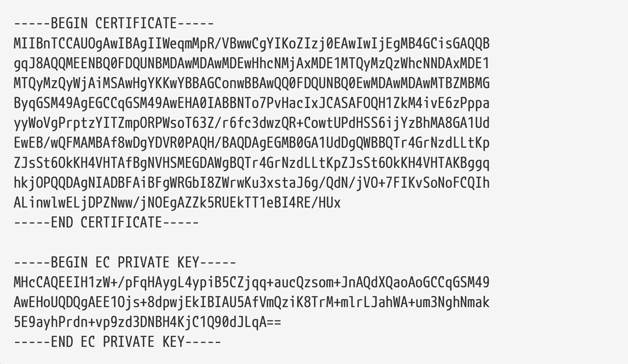
Certificate with Corresponding Private Key in an X.509 PEM Format
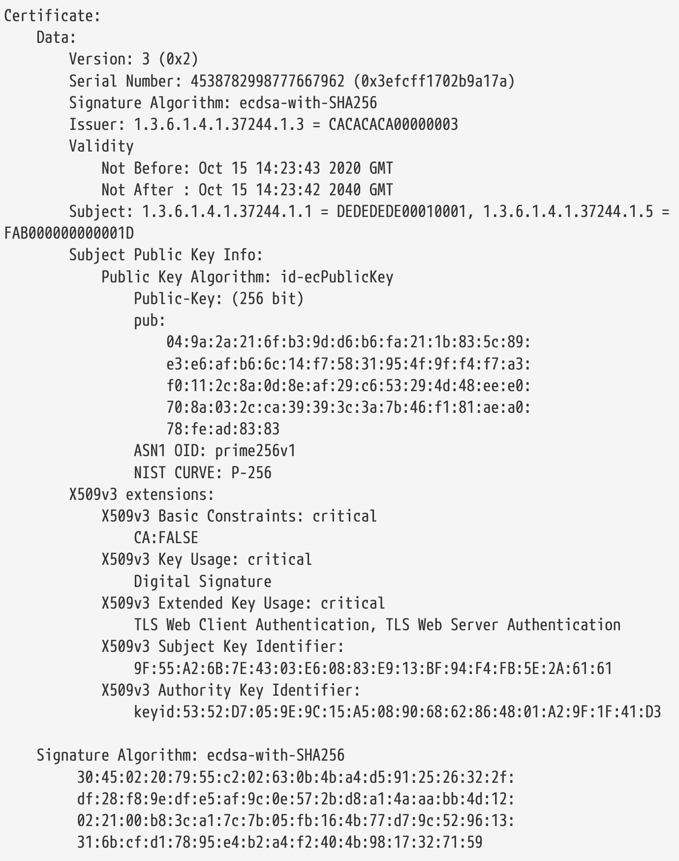
Certificate Printed in an X.509 DER Format
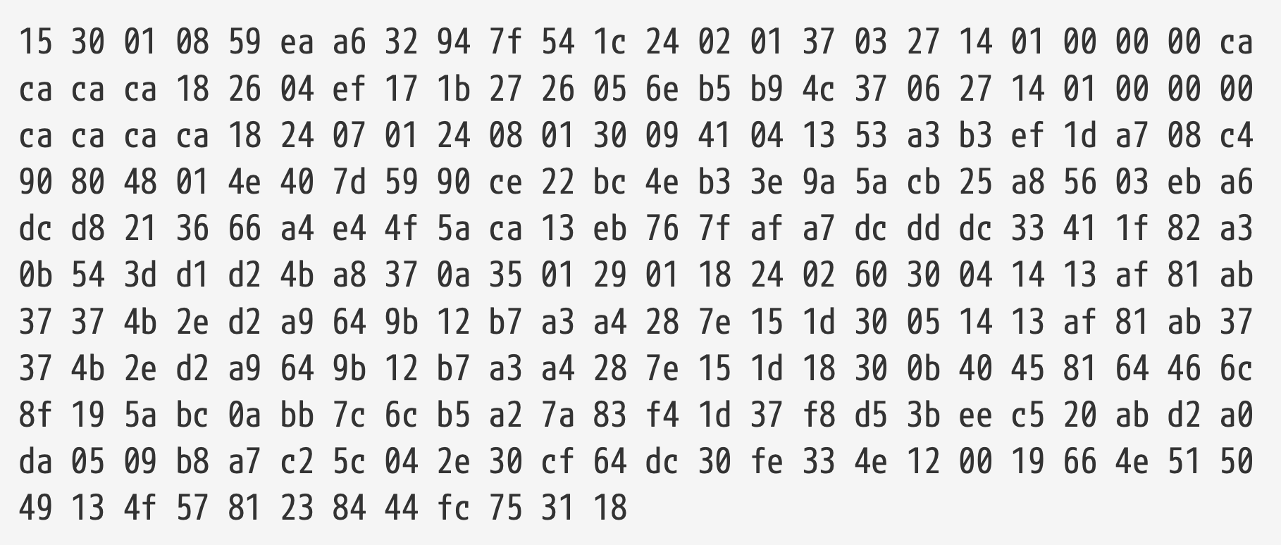
Certificate in Matter TLV Format
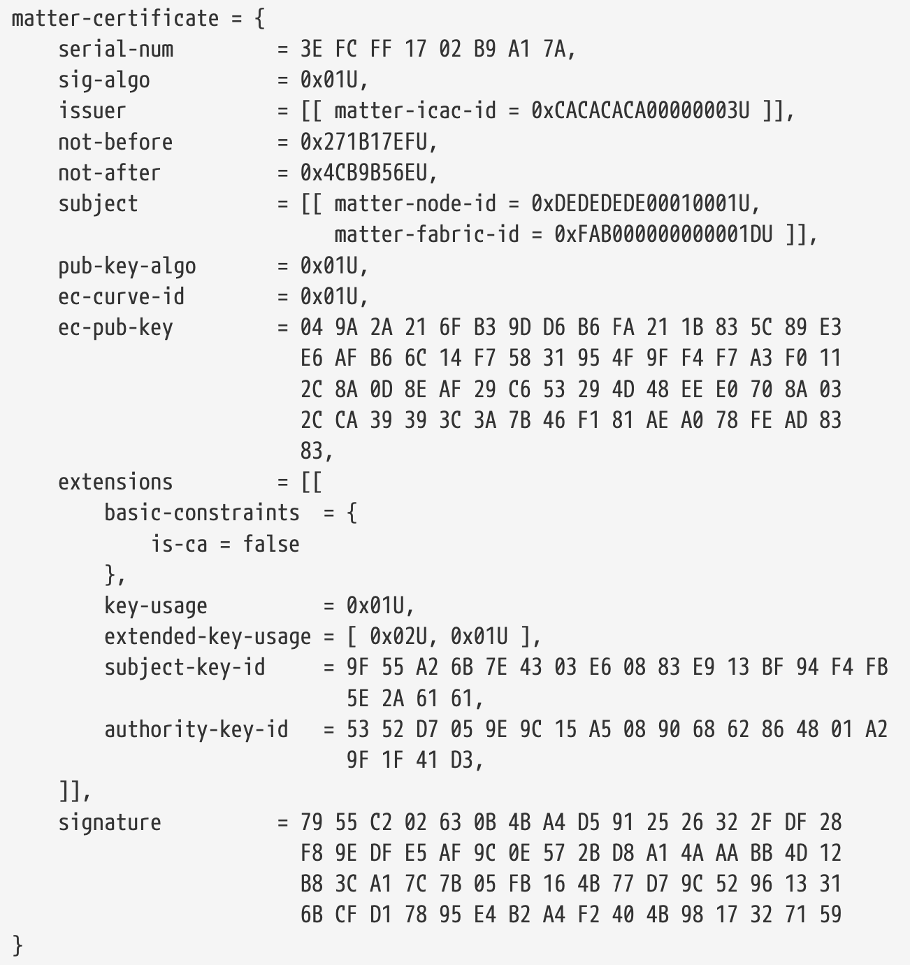
Certificate Printed in Matter TLV Schema Format
6.6. Access Control
6.6.1. Scope and Purpose
This section specifies the features related to controlling access to a Node’s Endpoint Clusters (“Targets” hereafter) from other Nodes. The overall features are collectively named “Access Control” hereafter.
The Access Control features aim to ensure that only authorized Nodes are permitted access to given application-layer functionality exposed by the
Data Model, through theInteraction Model. Access Control is the fundamental link between theSecure Channeland theInteraction Model.In order to implement a policy of Access Control, Administrators on the fabric create and maintain a consistent distributed configuration of Access Control Lists (ACLs) across all Nodes. Each Node has an ACL containing Access Control Entries which codify the policy. The Access Control Cluster exposes a data model view of a Node’s ACL which enables its maintenance.
6.6.2. Model
The Access Control system is rule-based with no implicit access permitted by default.
Access to a Node’s Targets is denied unless the Access Control system grants the required privilege level to a given Subject to interact with given Targets on that Node.
Initial Access Control privileges are bootstrapped during the commissioning phase, and maintained thereafter by Administrators.
6.6.2.1. Subjects
The meaning of a “Subject” is primarily that of describing the source for an action, using a given authentication method provided by the Secure Channel architecture.
6.6.2.2. Wildcards
The Subjects list of an Access Control Entry MAY grant a given privilege to more than one Subject, if the Authentication Mode allows it, such as in the case of the CASE and Group Authentication Modes.
6.6.2.3. Subjects do not correspond to users
6.6.2.4. Implementation-specific Rules
6.6.2.5. Incoming Subject Descriptors
6.6.2.6. Access Control Extensions
6.6.2.7. Application-level Permissions
6.6.2.8. Bootstrapping of the Access Control Cluster
6.6.2.9. Action attribution
6.6.2.10. Restrictions on Administer Level Privilege Grant
6.6.3. Access Control List Examples
Upon Factory Data Reset, the Access Control Cluster is empty, having an Access Control List with no entries:
Access Control Cluster: {
    ACL: [],      // empty
    Extension: [] // empty (omitted hereafter)
}
PASE commissioning channel during the commissioning phase, the following implicit Access Control Entry were present on the Commissionee (but not the Commissioner) to grant Administer privilege for the entire Node:
 Access Control Cluster: {
  ACL: [
    0: {                        // implicit entry only; does not explicitly exist!
      FabricIndex: 0,           // not fabric-specific
      Privilege: Administer,
      AuthMode: PASE,
      Subjects: [],
      Targets: []               // entire node
    }
  ]
}
During the commissioning phase, the AddNOC command automatically creates an Access Control Entry granting Administer privilege for the entire Node:
Access Control Cluster: {
    ACL: [
      0: {
        FabricIndex: 1,
        Privilege: Administer,
        AuthMode: CASE,
        Subjects: [ 0xAAAA_AAAA_AAAA_AAAA ],   // Node ID 0xAAAA_AAAA_AAAA_AAAA
        Targets: []
      }
    ]
}
An Administrator adds an Access Control Entry which grants View privilege, for the entire Node, to all CASE authenticated Nodes:
Access Control Cluster: {
  ACL: [
    ...
    1: {
        FabricIndex: 1,
        Privilege: View,
        AuthMode: CASE,
        Subjects: [],
        Targets: []
    }
  ]
}
An Administrator adds an Access Control Entry which grants Manage privilege, for endpoints 1 and 3, to any Nodes which can authenticate as members of Group 1:
Access Control Cluster: {
  ACL: [
    ...
    2: {
        FabricIndex: 1,
        Privilege: Manage,
        AuthMode: Group,
        Subjects: [ 0x0000_0000_0000_0001 ],
        Targets: [ { Endpoint: 1 }, { Endpoint: 3 } ]
    }
  ]
}
An Administrator revises this Access Control Entry to grant the same privilege, for only the pump configuration and control cluster (0x0202) on endpoint 3, and for any door lock cluster (0x0101) on the entire Node, to the same Nodes:
Access Control Cluster: {
  ACL: [
    ...
    2: {
        FabricIndex: 1,
        Privilege: Manage,
        AuthMode: Group,
        Subjects: [ 0x0000_0000_0000_0001 ],
        Targets: [ { Endpoint: 1 }, { Endpoint: 3, Cluster: 0x0000_0202 }, { Cluster: 0x0000_0101 } ]
    }
  ]
}
An Administrator adds an Access Control Entry which grants Operate privilege, for all endpoints containing the extended color light device (0x010D) on the entire Node, to CASE authenticated Nodes 0x1111_1111_1111_1111 and 0x2222_2222_2222_2222:
Access Control Cluster: {
  ACL: [
    ...
    3: {
        FabricIndex: 1,
        Privilege: Operate,
        AuthMode: CASE,
        Subjects: [ 0x1111_1111_1111_1111, 0x2222_2222_2222_2222 ],
        Targets: [ { DeviceType: 0x0000_010D } ]
    }
  ]
}
6.6.4. Access Control Cluster update side-effects
Updates to the Access Control Cluster SHALL take immediate effect in the Access Control system.
6.6.5. Conceptual Access Control Privilege Granting Algorithm
This section describes an overall Conceptual Access Control Privilege Granting algorithm.
Implementations of this algorithm SHALL have an identical outcome to the output of this conceptual algorithm described below.
6.6.5.1. Necessary Data Structures
6.6.5.1.1. Access Control List
The Access Control List contains several Access Control Entries:
• Subjects List (SubjectID[] Subjects)
• Targets List (TargetStruct[] Targets)
• Authentication Mode value (AuthModeEnum AuthMode)
• Privilege value (PrivilegeEnum Privilege)
6.6.5.1.2. Incoming Subject Descriptor (ISD) Structure
Each incoming message has a unique <AuthMode, SubjectDescriptor> applicable to it, whose derivation is deterministic based on both incoming message fields and session metadata fields.
The ISD fields are as follows:
• Commissioning Flag (`bool IsCommissioning`),
    whether the authentication is over a commissioning channel.
• Authentication Mode (`AuthModeEnum AuthMode`),
    mapping to an authentication mode
• Subjects List (`list<SubjectID> Subjects`),
    mapping incoming message source to a type of subject
• Fabric Index (`FabricIndex FabricIndex`),
    mapping to a fabric reference.
6.6.5.2. Overall Algorithm
The algorithm takes as input:
• the ISD of Incoming Message (`subject_desc`)
• the Endpoint ID (`endpoint_id`) for which the querier requires a Privilege level
• the Cluster ID (`cluster_id`) for which the querier requires a Privilege level
• the Access Control List (`acl`) from the Access Control Cluster
The output of the algorithm is:
• A set of privileges granted for the Action Path,
    which is a subset of {View, ProxyView, Operate, Manage, Administer}
6.6.5.3. Derivation of ISD from Incoming Message
The algorithm to derive the ISD from an incoming message takes as input:
• The incoming message (`message`)
• The Session ID of the incoming message (`session_id`)
• A conceptual Sessions Metadata database (`sessions_metadata`)
• The Group Key Management Cluster (`group_key_management_cluster`)
The output of the algorithm is the SubjectDescriptor structure below::
DEFAULT_COMMISSIONING_PASSCODE = 0

enum AuthModeEnum {
    None = 0, # conceptual "no auth" value
    PASE = 1,
    CASE = 2,
    Group = 3
}

struct SubjectDescriptor {
    bool IsCommissioning;
    AuthModeEnum AuthMode;
    list<SubjectID> Subjects; # max 3 items
    FabricIndex FabricIndex;
}
6.6.6. Applying Privileges to Action Paths
The Data Model specifies which privilege is required for each data element, via its access qualities.
Chapter 7. Data Model Specification
7.1. Practical Information
This is part of a package of Data Model specifications that are agnostic to underlying layers (encoding, message, network, transport, etc.).
Each specification below may be independently maintained.
This package, as a whole, shall be independently maintained as agnostic and decoupled from lower layers.
This package may be referenced by inclusion in vertical protocol stack specifications.
• Data Model
    Defines first order elements and namespace for
        endpoints, clusters, attributes, data types, etc.
• Interaction Model
    Defines interactions, transactions and actions between nodes.
• System Model
    Defines relationships that are managed between endpoints and clusters.
• Cluster Library
    Reference library of cluster specifications.
• Device Library
    Reference library of device type specifications.
The origin of this section is the
Dotdot Architecture Model[Dotdot Architecture] and parts of Chapter 2 of theZigbee Cluster Library specification[ZCL] that define the data model.This document defines first order elements and namespace of the data model and can also be called the
meta-model(of the data model). This document is the “read me first” specification in the data model. This data model is ultimately implemented in the application layer of a communication stack.
Glossary:
MS:     Manufacturer or Vendor Specific
N/A:    not applicable
desc:   see detailed description section
7.2. Data Qualities
Cluster specifications and device type definitions have tables that define the qualities of elements that make up the cluster or device type.
7.2.1. Common Data Table Columns:
• ID
• Name
• Field:
    Same as Name. deprecated
    Other headers like "Field", "Bit Field", and "Command Field", are deprecated.
    UseName.
• Conformance:
    Defines dependencies on whether an element is optional or mandatory.
• Access:
    Defines how an element is accessed (e.g. read or write)
    and what privileges are required to access the data.
7.2.2. Other Data Table Columns:
• Data Type
    A data field requires this column for attribute, event or command data.
• Other Qualities
    This is a catchall column for uncategorized qualities.
• Default
    This defines a default value for data fields.
• Response
    Cluster command tables have this column.
• Direction
    Cluster command tables have this column.
• Priority
    Event tables have this column.
• Value
    Enumerations use this column instead of the ID column.
7.3. Conformance
A Conformance column defines optionality and dependency for any data model element or set of elements.
Conformance Column:
M: Mandatory
O: Optional
P: Provisional
D: Deprecated
X: Disallowed

AB:         Mandatory
[AB]:       Optional
EF:         Operand
EF==v:      Equal
EF!=v:      Unequal
AB | CD:    Or
AB ^ CD:    Xor
AB & CD:    And
!AB:        Exclusivity
(AB & CD):  Parenthese
C1, C2...   List
C.an        Choice
List Conformance:
• "AB, O" means mandatory for AB and optional otherwise.
• "AB, [CD]" means mandatory for AB, optional if CD is true and AB is false, otherwise not allowed.
• "!AB, O" means mandatory if AB is false, otherwise optional (if AB is true).
• "[AB], M" is the equivalent to "!AB, O", and a clearer way to define the conformance.
• "[AA], [BB], [CC]" is the equivalent to "[AA | BB | CC]".
Choice Conformance:
• "AB.a" means only one of the "a" elements SHALL be supported.
• "AB.a2" means exactly two of the "a" elements SHALL be supported.
• "AB.a2+" means at least two of the "a" elements SHALL be supported.
• "AB.a+" means at least one of the "a" elements SHALL be supported.
7.4. Element
Listed below are the elements of the data model:
• First order elements
    fabric, node, endpoint, cluster
• Cluster first order elements
    command, event, attribute
• Nested elements
    command field, event field, struct field
• Dynamic element
    list entry
• Semantic elements
    device type, data type
• Attribute data
    elements (above) that are part of an attribute
• Data field
    attribute, field element, or list entry (see Data Field)
7.5. Fabric
A fabric is set of nodes that interact by accessing data model elements as defined in the Interaction Model. A fabric is a security domain that allows a set of nodes to be identified and communicate within the context of the domain.
7.6. Access
An Access column defines access to a data model element or set of elements:
• R       Read Access
• W       Write Access
• R[W]    Read Access and optionally Write Access
• R*W     Deprecated: use R[W]

Fabric - separate with space from RW:
• F Fabric-Scoped Quality
• S Fabric-Sensitive Quality

Privileges - separate with space from RW FS:
• V    View privilege
• O    Operate privilege
• M    Manage privilege
• A    Administer privilege

Timed - separate with space from RW FS VOMA
• T    Write Access or Invoke Access with timed interaction only
7.7. Other Qualities
Some qualities are limited to a specific set of elements:
• X   Nullable        data fields
• N   Non-Volatile    attribute data
    the attribute data value is non-volatile and is persistent across restarts
• F   Fixed           attribute data
    the read only value is a fixed value that never changes, unless the program image changes
• S   Scene           attribute
    the attribute is part of a scene
• P   Reportable      attribute
• C   Changes Omitted    attribute data
• I   Singleton           device type
• !Q  Disalow             device type
7.8. Node
A Node encapsulates an addressable, unique resource on the network that has a set of functions and capabilities that a user recognizes distinctly as a functional whole.
7.9. Endpoint
A node is composed of one or more endpoints. An endpoint is an instance of something that could be a service or virtual device as indicated by a device type.
7.10. Cluster
Clusters are the functional building block elements of the data model.
A cluster specification defines both a client and server side that correspond with each other through interactions.
A cluster may be considered an interface, service, or object class and is the lowest independent functional element in the data model.
Each cluster is defined by a cluster specification that defines elements of a cluster including attributes, events, commands, as well as behavior associated with interactions with these elements.
The server cluster supports
attribute data,eventsandcluster commands.The client cluster initiates interactions, including invocation of
cluster commands.
Cluster Classification:
1. Utility Cluster
    It may be used for:
        • configuration,
        • discovery,
        • addressing,
        • diagnostics,
        • monitoring device health,
        • software update,
        • etc.
    It may have a temporary relationship with its cluster counterpart.
    examples:
         scoped to an `endpoint`: Identify, Descriptor, Binding, Groups, etc.
         scoped to the `node`: Basic Information, Diagnostics, etc.
2. Application Cluster
    It supports the primary operation of the endpoint.
    It supports one or more persistent application interactions between client and server.
    Example application cluster transactions:
        • On/Off cluster - client sends command to server
        • Temperature Measurement cluster - server reports data to client
7.11. Command
A cluster command is a set of data fields, each of a data type that is conveyed between client and server cluster instances to invoke a behavior on the receiver of the command.
Each command SHALL be listed in a table with data quality columns:
• ID,
• Name,
• Direction,
• Response,
• Access,
• Conformance.
A cluster command table SHALL have a Response column with the following values:
• N:         no response is returned for this command
• Y:         status only is returned for this command
• command:   name of the response command to this command
A cluster command table SHALL have a Direction column with the following values:
• client ⇒ server
• client ⇐ server
Command Fields:
• ID           This is the unique field ID of the field
• Name         This is the unique name of the field
• Type         This is the data type of the field
• Constraint   see `Constraint`
• Quality      see `qualities`
• Default      see `Default`
• Conformance  see `Conformance`
7.12. Attribute
An attribute is cluster data.
Each attribute SHALL be listed in a table with data quality columns:
ID,Name,(Data) Type,Constraint,other Quality,Access,Default (value), andConformance.Persistent data retains its value across a restart(except factory reset).
7.13. Global Elements
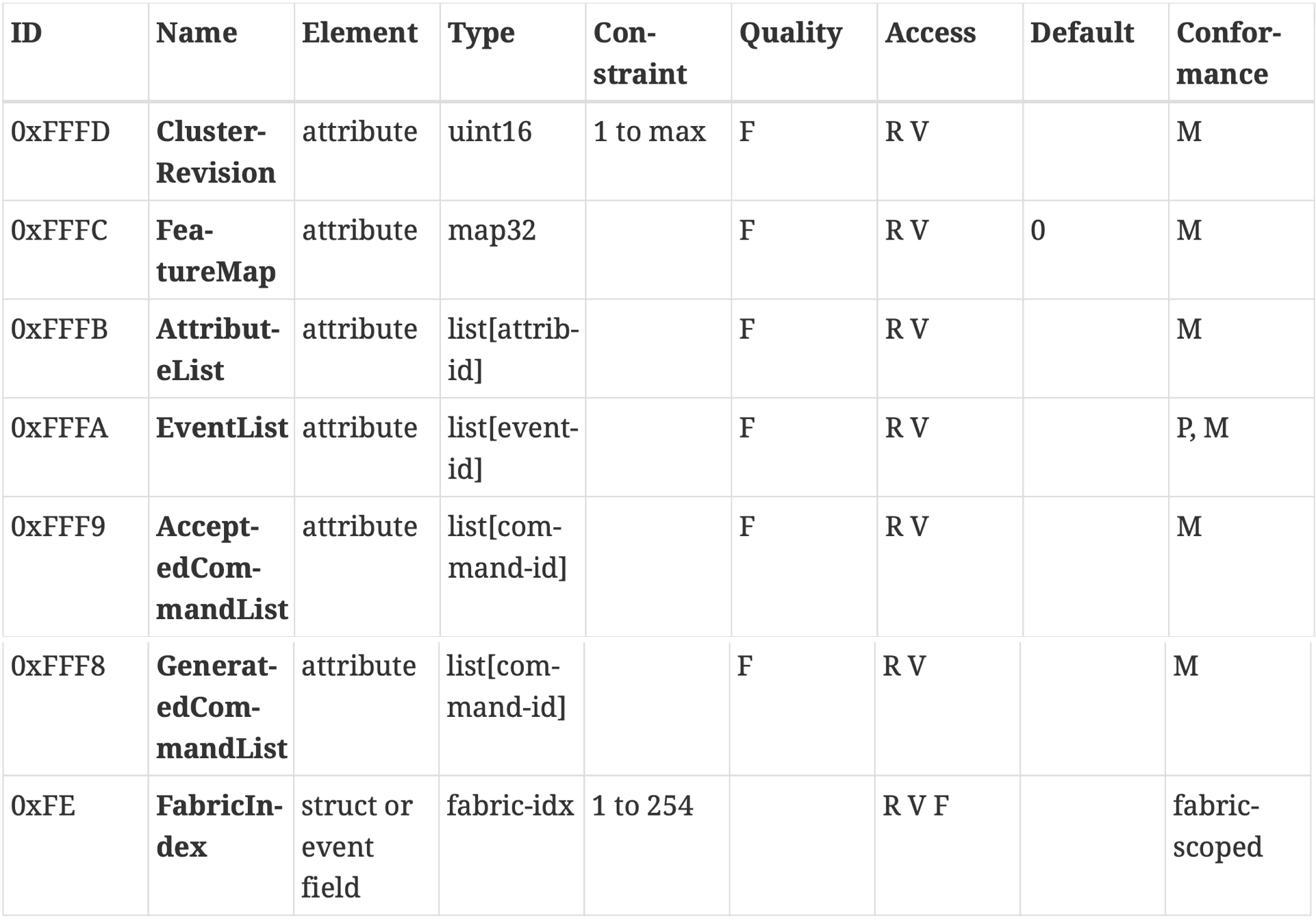
list of global elements used for self-description of the server.
7.14. Event
An event defines a record of something that occurred in the past.
In this regard, an event record can be thought of as a log entry, with an event record stream providing a chronological view of the events on the node.
Priority:
DEBUG
INFO
CRITICAL
Event Record SHALL have the following data fields associated with it that are common to all events:
• Event Number
• Timestamp
• Priority
7.15. Device Type
In this architecture model, a device type is the highest semantic element.
A device type defines conformance for a set of one or more endpoints.
A device type defines a set of requirements for the node or endpoint in the market.
7.16. Non-Standard
This architecture model provides mechanisms for non-standard or manufacturer specific items such as clusters, commands, events, attributes and attribute data fields.
7.17. Data Field
A data field is any
attribute,fieldorentrythat is not a collection data type, or data that is not surfaced as an attribute, but defined in a cluster specification.Each cluster
data fieldSHALL be defined with a table including these columns for data qualities:• Data Type • Constraint • Quality • Access • Default • Conformance
Common Literal Values:
0
1
FALSE
TRUE
NaN
null
empty
min
max
numeric units
Constraint:
x
x to y
max y
min x
all
Default Value:
• If the data field is nullable then the default value SHALL be null
• Else the default value SHALL be one of the following, depending on type:
    ◦ Boolean: false
    ◦ Analog: 0 or 0.0, depending on range ◦ Bitmaps: 0
    ◦ Enumeration: MS
    ◦ Composite:
        ▪ String: empty
        ▪ List: empty
        ▪ Struct: default is recursively composited from the defaults of its member fields
    ◦ Derived types: use the default value of the base type
7.18. Data Types
Each data field in a cluster specification SHALL have a well-defined data type.
Each attribute in a cluster specification SHALL map to a single data type.
Base Data Types:
• Discrete
    ◦ Boolean
    ◦ Bitmap
• Analog
    ◦ Unsigned Integer
    ◦ Signed Integer
    ◦ Floating Point
• Composite
    ◦ String
    ◦ Collection
        ▪ List
        ▪ Struct
Derived Data Types:
• Analog
    ◦ Relative
        ▪ percent
    ◦ Time
        ▪ Date(struct)
        ▪ UTC Time(uint32)
• Discrete
    ◦ Enumeration
        ▪ Status Code
        ▪ Priority
    ◦ Identifier
        ▪ Fabric ID
        ▪ Node ID
        ▪ ...
    ◦ Index
        ▪ Entry Index
    ◦ Counter
        ▪ Data Version
        ▪ Event Number
• Composite
    ◦ String
    ◦ Address
        ▪ IP Address
        ▪ Hardware Address
▪ Status Code:
0x00 common status code: SUCCESS
0x01 common status code: FAILURE
0x02 to 0x10 cluster scoped status codes
0x70 to 0xCF other common status codes defined in Interaction Model Status Code Table.
▪ Priority:
0 DEBUG
1 INFO
2 CRITICAL
▪ IP Address:
• Address 192.168.2.235 → C0A802EB
• Address 10.4.200.75 → 0A04C84B
• Address 2001:DB8:0:0:8:800:200C:417A → 20010DB80000000000080800200C417A
• Address 2001:0DB8:1122:3344:5566:7788:99AA:BBCC → 20010DB8112233445566778899AABBCC
7.19. Manufacturer Specific Extensions
This section covers Manufacturer Specific (MS) extensions and how they are supported by identifiers, paths, wildcards, discoverability, etc.
Chapter 8. Interaction Model Specification
8.1. Practical Information
The purpose is to define a layer that abstracts interactions from other layers, including security, transport, message format & encoding.
Glossary:
• Wildcardable(A)
• Optional(O)
• Quality(Qual, Q)
• Action Flow
• Supported
• Unsupported
• Path
a path to an element
• Group Path
a path with a group ID instead of node ID and endpoint number
• Wildcard Path
a path with one or more elements that are wildcards
• Attribute Path
a path to an attribute data field path for attribute data
• Request Path
a path that may be a group or wildcard path
(of course may be a Concrete Path)
• Concrete Path
a path that is not a group or wildcard path
• Existent Path
a concrete path that exists on a server cluster
8.2. Concepts
Relationships between devices are established using data model elements and interactions defined here.
An interaction is a sequence of transactions. A transaction is a sequence of actions.
An action is a single logical communication from a source node to one or more destination nodes. An action is conveyed by one or more messages.
The actual construction and encoding of messages is left to the message layer, which is the layer below this layer.
8.2.1. Path
A path is used to indicate one or more element instances in the data model. The path has the form as described in Augmented Backus–Naur:
• <path> ::= <target> <cluster> <cluster element>
• <target> ::= <group target> | <endpoint target>
• <group target> ::= <group ID>
• <endpoint target> ::= <node> <endpoint>
• <endpoint> ::= <wildcard endpoint> | <concrete endpoint>
• <cluster> ::= <wildcard cluster> | <concrete cluster>
• <cluster element> ::= <attribute> | <event> | <command>
An Attribute Path is a path indicating an <attribute>:
<attribute> ::= <attribute ID> <nesting level>*
<nesting level> ::= <struct field ID> | <list entry index>
A Command Path is a path indicating a <command>:
<command> ::= <command ID>
An Event Path is a path indicating an <event>:
<event> ::= <event ID>
8.2.2. Interaction
An interaction is a sequence of one or more transactions between nodes, that occurs in the context of an accessing fabric, or no fabric.
An interaction may be a single transaction (e.g. Read).
An interaction may be an unbounded number of transactions (e.g. Subscribe)
Interaction |
Transactions |
|---|---|
Read Interaction |
Read |
Subscribe Interaction |
Subscribe, Report |
Write Interaction |
Write |
Invoke Interaction |
Invoke |
8.2.3. Transaction
A transaction is either the whole, or part of an interaction. A transaction is a sequence of one or more actions.
8.2.4. Action
all actions:
• Status Response Action
• Read Request Action
• Report Data Action
• Subscribe Request Action
• Subscribe Response Action
• Write Request Action
• Write Response Action
• Invoke Request Action
• Invoke Response Action
• Timed Request Action
8.2.5. Common Action Behavior
Common Action Information:
• InteractionModelRevision
• Action
• TransactionID
• FabricIndex
• SourceNode
• DestinationNode/DestinationGroup
• action specific
Outgoing Action
Incoming Action
8.3. Status and Interaction
There is no Status interaction, but an error status may be generated as part of any interaction.
8.3.1. Status Response Action
This action is defined as a following action for some actions, or is generated when there is an unspecified transaction or interaction error.
8.4. Read Interaction
This interaction is generated when an initiator wishes to determine the value of one or more attributes or events located on a node.
8.4.1. Read Transaction
• Read Request Initiator ⇒ Target
• Report Data Initiator ⇐ Target
8.4.2. Read Request Action
Read Request Action Information:
• AttributeRequests
• DataVersionFilters
• EventRequests
• EventFilters
• FabricFiltered
8.4.3. Report Data Action
Report Data Action Information:
• SuppressResponse
• SubscriptionId
• AttributeReports
• EventReports
8.5. Subscribe Interaction
The Subscribe interaction is composed of these transactions: +————–+—————————————————————–+ | Transaction | Description | +==============+=================================================================+ | Subscribe | start and prime a reporting session | +————–+—————————————————————–+ | Report | synchronized Report transaction | +————–+—————————————————————–+ | more reports | continuous Report transactions for the life of the subscription | +————–+—————————————————————–+
8.5.1. Subscribe Transaction
• Subscribe Request Initiator ⇒ Target
• Report Data Initiator ⇐ Target
• Status Response Initiator ⇒ Target
• Subscribe Response Initiator ⇐ Target
8.5.2. Subscribe Request Action
Subscribe Request Action Information:
• KeepSubscriptions
• MinIntervalFloor
• MaxIntervalCeiling
• AttributeRequests
• DataVersionFilters
• EventRequests
• EventFilters
• FabricFiltered
8.5.3. Subscribe Response Action
Subscribe Response Action Information:
• SubscriptionId
• MaxInterval
8.6. Report Transaction
There is no Report interaction. A Report transaction is part of a Subscribe interaction.
8.6.1. Report Transaction Non-Empty
• Report Data Initiator ⇐ Target
• Status Response Initiator ⇒ Target
8.6.2. Report Transaction Empty
• Report Data Initiator ⇐ Target
8.7. Write Interaction
This interaction is started when an initiator wishes to modify the values of one or more attributes located on one or more nodes.
8.7.1. Write Transaction
Timed Write Transaction:
• Timed Request Initiator ⇒ Target
• Status Response Initiator ⇐ Target
• Write Request Initiator ⇒ Target
• Write Response Initiator ⇐ Target
Untimed Write Transaction:
• Write Request Initiator ⇒ Target
• Write Response Initiator ⇐ Target
8.7.2. Write Request Action
Write Request Action Information:
• SuppressResponse
• TimedRequest
• WriteRequests
8.7.3. Write Response Action
Write Response Action Information:
• WriteResponses
8.7.4. Timed Request Action
This action informs the receiver that another action will be sent in the same direction, within the same transaction, and within a specified Timeout interval. The Timeout interval SHALL start when the Status Response action acknowledging the Timed Request action with a success code is sent.
Timed Request Action Information:
• Timeout
8.8. Invoke Interaction
This interaction is generated when a device wishes to invoke one or more cluster specific commands on one or more nodes. Cluster commands are defined as either client to server or server to client. Invoke Request action SHALL support group paths and SHOULD support wildcard paths. Invoke Response action does not support wildcard paths.
8.8.1. Invoke Transaction
Timed Invoke Transaction:
• Timed Request Initiator ⇒ Target
• Status Response Initiator ⇐ Target
• Invoke Request Initiator ⇒ Target
• Invoke Response Initiator ⇐ Target
• ... Initiator ⇐⇒ Target
Untimed Invoke Transaction:
• Invoke Request Initiator ⇒ Target
• Invoke Response Initiator ⇐ Target
• ... Initiator ⇐⇒ Target
8.8.2. Invoke Request Action
Invoke Request Action Information:
• SuppressResponse
• TimedRequest
• InvokeRequests
8.8.3. Invoke Response Action
Invoke Response Action Information:
• SuppressResponse
• InvokeResponses
8.9. Common Action Information Blocks and Paths
8.9.1. Path Information
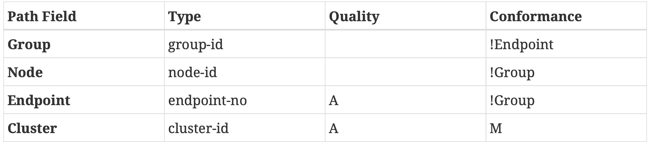
ClusterPathIB
8.9.2. Attribute Information Blocks
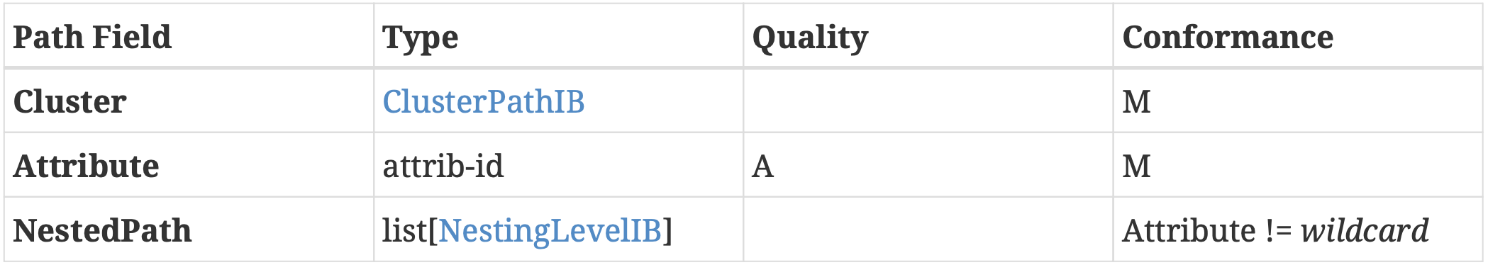
AttributePathIB
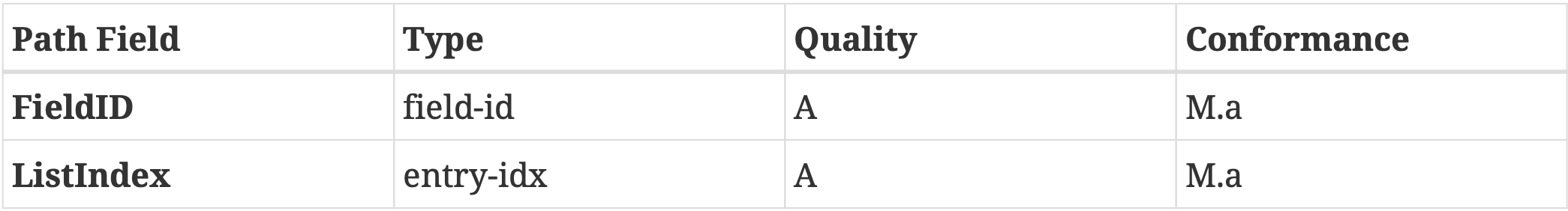
NestingLevelIB
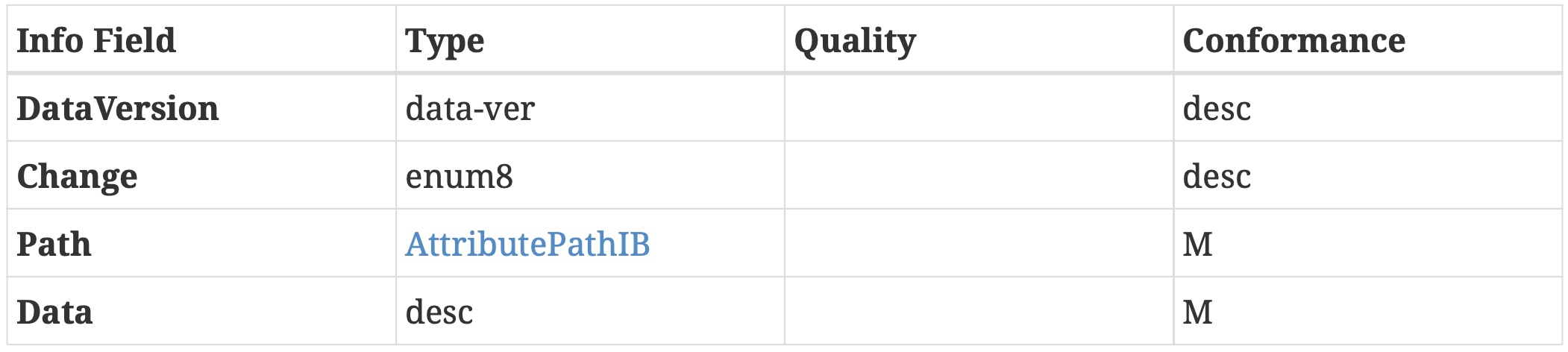
AttributeDataIB
Change field indicates a change to a list for a write interaction:
REPLACE
ADD
DELETE
MODIFY
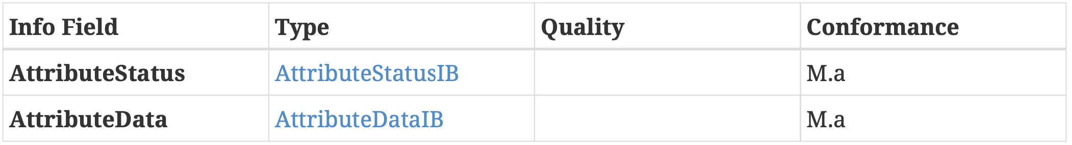
AttributeReportIB
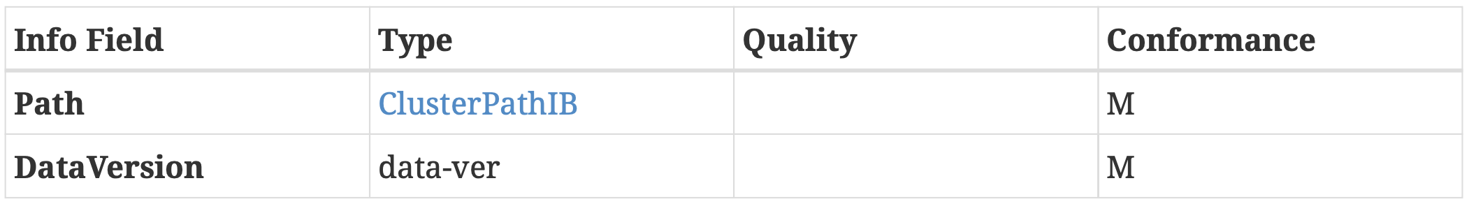
DataVersionFilterIB
8.9.3. Event Information Blocks and Paths
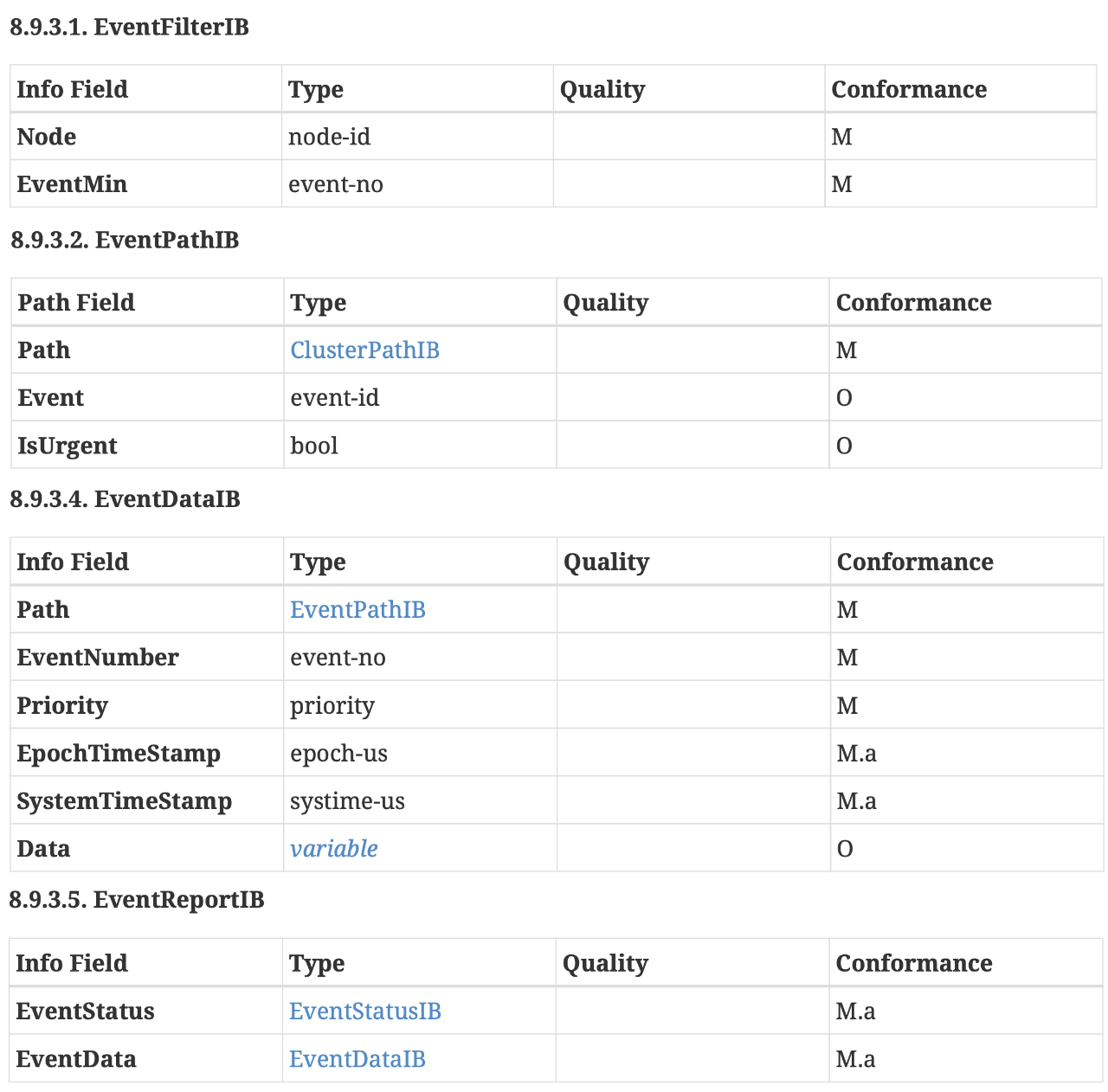
EventFilterIB, EventPathIB, EventDataIB, EventReportIB
8.9.4. Command Information Blocks and Paths
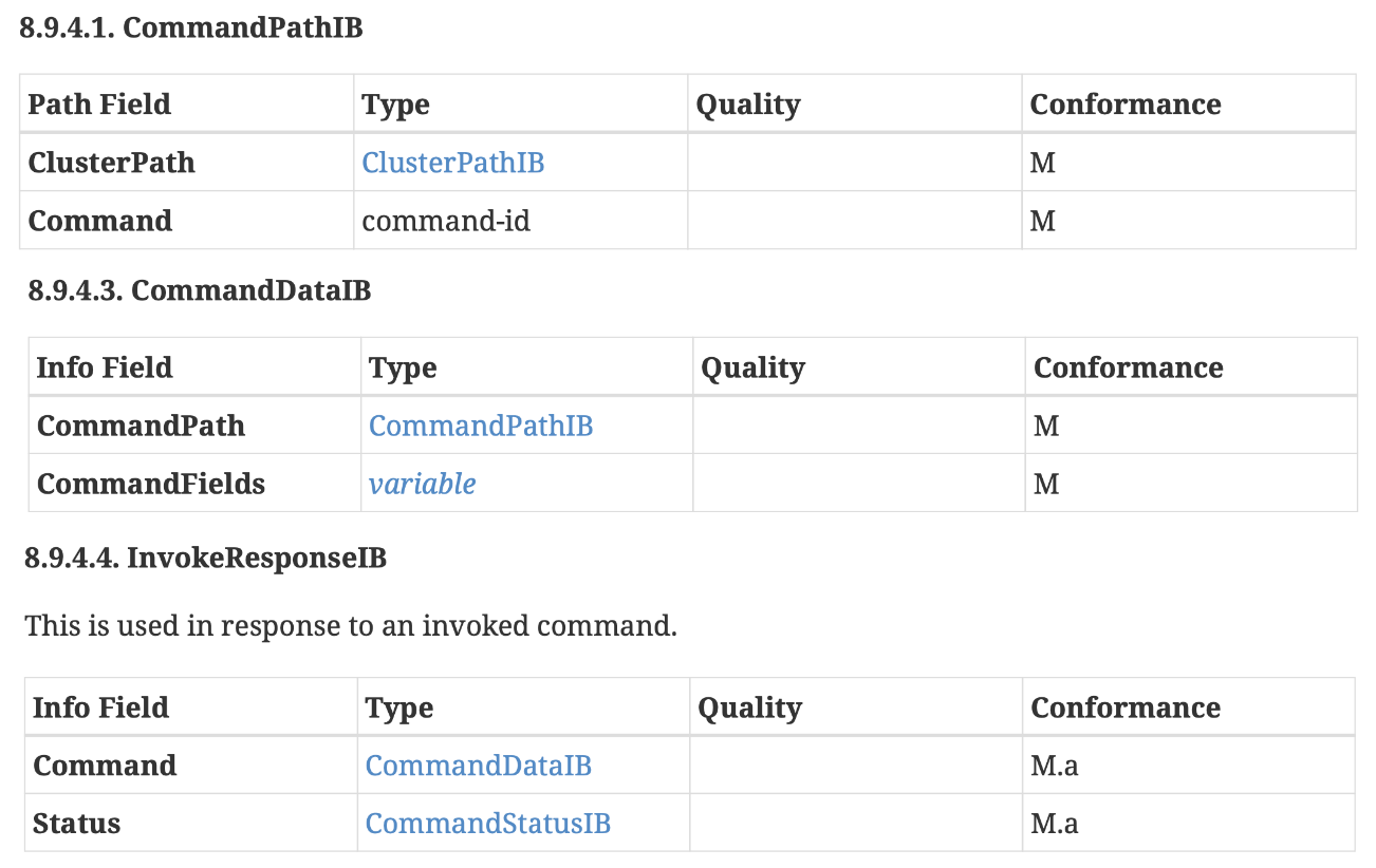
CommandPathIB, CommandDataIB, InvokeResponseIB
8.9.5. Status Information Blocks and Paths
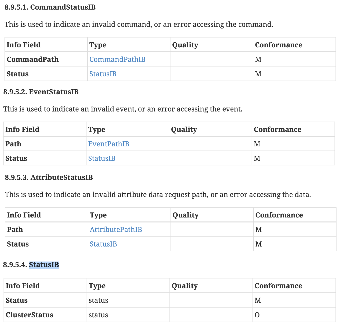
CommandStatusIB, EventStatusIB, AttributeStatusIB, StatusIB
8.10. Status Codes
Status Code |
Value |
|---|---|
SUCCESS |
0x00 |
FAILURE |
0x01 |
INVALID_SUBSCRIPTION |
0x7D |
UNSUPPORTED_ACCESS(NOT_AUTHORIZED) |
0x7E |
UNSUPPORTED_ENDPOINT |
0x7F |
INVALID_ACTION |
0x80 |
UNSUPPORTED_COMMAND(UNSUP_COMMAND) 0x81 |
|
reserved |
0x82 |
reserved |
0x83 |
reserved |
0x84 |
INVALID_COMMAND(INVALID_FIELD) |
0x85 |
UNSUPPORTED_ATTRIBUTE |
0x86 |
CONSTRAINT_ERROR(INVALID_VALUE) |
0x87 |
UNSUPPORTED_WRITE READ_ONLY |
0x88 |
RESOURCE_EXHAUSTED(INSUFFICIENT_SPACE) |
0x89 |
reserved |
0x8A |
NOT_FOUND |
0x8B |
UNREPORTABLE_ATTRIBUTE |
0x8C |
INVALID_DATA_TYPE |
0x8D |
reserved |
0x8E |
UNSUPPORTED_READ |
0x8F |
reserved |
0x90 |
reserved |
0x91 |
DATA_VERSION_MISMATCH |
0x92 |
reserved |
0x93 |
TIMEOUT |
0x94 |
reserved |
0x95 |
reserved |
0x96 |
reserved |
0x97 |
reserved |
0x98 |
reserved |
0x99 |
reserved |
0x9A |
UNSUPPORTED_NODE |
0x9B |
BUSY |
0x9C |
reserved |
0xC0 |
reserved |
0xC1 |
reserved |
0xC2 |
UNSUPPORTED_CLUSTER |
0xC3 |
reserved |
0xC4 |
NO_UPSTREAM_SUBSCRIPTION |
0xC5 |
NEEDS_TIMED_INTERACTION |
0xC6 |
UNSUPPORTED_EVENT |
0xC7 |
PATHS_EXHAUSTED |
0xC8 |
TIMED_REQUEST_MISMATCH |
0xC9 |
FAILSAFE_REQUIRED |
0xCA |
Chapter 9. System Model Specification
9.1. Practical Information
备注
Defines relationships that are managed between endpoints and clusters.
This specification defines persistent relationships between local and remote instances of data model elements, that support a system of operational communication between such instances.
A system is a set of nodes and persistent relationships that automate data flow and control based on local or external stimulus.
9.2. Endpoint Composition
Endpoint composition SHALL be indicated by these Descriptor cluster attributes:
• `DeviceTypeList` SHALL list the device type(s) that the endpoint supports
• `PartsList` SHALL indicate the endpoints that support these device type(s)
Each simple endpoint SHALL support only one Application device type with these exceptions:
• The endpoint MAY support additional device types
which are subsets of the Application device type (the superset).
• The endpoint MAY support additional device types
as defined by each additional device type.
9.2.1. Dynamic Endpoint allocation
Some nodes MAY require a dynamic number of endpoints, since the functionality they expose can change at run-time:
• a Bridge on which Bridged Devices are added or deleted.
• a Casting Video Player in which Content Apps are added or deleted
9.3. Interaction Model Relationships
This section define some of the system behaviors and their constraints as they apply to interactions specified in the Interaction Model.
9.3.1. Subscription
A subscription is an ephemeral ‘session’ between a subscriber and a publisher.
In all cases, the
subscribercan eventually discover the loss of synchronization by not receiving a sync report or data report in the agreed upon sync interval, or through some other failure to communicate with the publisher.In all cases, the
publishereventually discovers the loss of synchronization by not receiving a Status Response to a Report Data message that expects a response, or by receiving an error Status Response.
9.4. Binding Relationship
This relationship occurs because a simple client endpoint does not know which endpoints will be the target for the client generated actions, on one or more remote nodes.
For example: A light switch that controls one or more light bulbs, does not know the remote node endpoints of the bulbs.
9.5. Descriptor Cluster
This cluster describes an endpoint instance on the node, independently from other endpoints, but also allows composition of endpoints to conform to complex device type patterns.
This cluster supports a list of one or more device type identifiers that represent conformance to device type specifications.
Attributes:
• 0x0000 DeviceTypeList list[DeviceTypeStruct]
• 0x0001 ServerList list[cluster-id]
• 0x0002 ClientList list[cluster-id]
• 0x0003 PartsList list[endpoint-no]
9.6. Binding Cluster
A binding represents a persistent relationship between an endpoint and one or more other local or remote endpoints. A binding does not require that the relationship exists. It is up to the node application to set up the relationship.
A binding is used to inform a client endpoint of one or more targets for a potential interaction. For example: a light switch that controls one or more light bulbs, needs to be told the nodes and endpoints of the bulbs, or told a group in which the bulbs are members.
In such cases, a binding is used to direct a local endpoint to a target. The existence of the Binding cluster on the client endpoint, allows the creation of one or more binding entries (bindings) in the Binding cluster.
A binding is either a unicast binding, where the target is a single endpoint on a single node, or a groupcast binding, where the target is a group, which may indicate multiple endpoints on multiple nodes.
Attributes:
• 0x0000 Binding list[``TargetStruct``]
Binding Attribute Examples:
• Light Switch Client:
switch endpoint sends `On/Off`, `Level & Color Control` cluster commands to group 1234
• Temp Sensor Client:
temperature sensor client subscribes to
`node 456789` `endpoint 3` temperature measurement cluster
TargetStruct Data Types:
Node
Group
Endpoint
Cluster
9.7. Label Cluster
This cluster provides a feature to tag an endpoint with zero or more labels. This is a base cluster that requires a derived cluster to create an instance.
Attributes:
• 0x0000 LabelList list[``LabelStruct``]
LabelStruct Data Types:
Label
Value
9.8. Fixed Label Cluster
This cluster provides a feature for the device to tag an endpoint with zero or more read only labels.
9.9. User Label Cluster
This cluster provides a feature to tag an endpoint with zero or more labels.
9.10. Access Control Cluster
The
Access Control Clusterexposes a data model view of a Node’sAccess Control List (ACL), which codifies the rules used to manage and enforce Access Control for the Node’s endpoints and their associated cluster instances.Access to this
Access Control Clusteritself requires a special Administer privilege level, such that only Nodes granted such privilege (hereafter termed “Administrators”) can manage the Access Control Cluster.
Attributes
Attributes:
• 0x0000 ACL list[`AccessControlEntryStruct`]
• 0x0001 Extension list[`AccessControlExtensionStruct`]
• 0x0002 SubjectsPerAccessControlEntry uint16
• 0x0003 TargetsPerAccessControlEntry uint16
• 0x0004 AccessControlEntriesPerFabric uint16
AccessControlEntryStruct Data Types:
• Privilege AccessControlEntryPrivilegeEnum
View
Proxy View
Operate
Manage
Administer
• AuthMode AccessControlEntryAuthModeEnum
PASE
CASE
Group
• Subjects list[SubjectID]
• Targets list[`TargetStruct`]
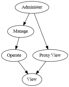
Figure 39. Access Control Privilege Levels
Table 78. AuthModeEnum:
Value Name Description
1 PASE Passcode authenticated session
2 CASE Certificate authenticated session
3 Group Group authenticated session
Table 79. Subject Semantics:
AuthMode Subject
PASE Lower 16-bits → Passcode ID
Upper 48-bits → all bits clear
CASE 64-bits → Node ID
or CASE Authenticated Tag
Group Lower 16-bits → Group ID
Upper 48-bits → all bits clear
TargetStruct sub Data Types:
Cluster
Endpoint
DeviceType
AccessControlExtensionStruct Data Types:
• Data octstr Type
Events
This cluster SHALL support these events:
• AccessControlEntryChanged
• AccessControlExtensionChanged
AccessControlEntryChanged Event:
• 1 AdminNodeID node-id
• 2 AdminPasscodeID uint16
• 3 ChangeType ChangeTypeEnum
• 4 LatestValue AccessControlEntryStruct
AccessControlExtensionChanged Event:
• 1 AdminNodeID node-id
• 2 AdminPasscodeID uint16
• 3 ChangeType ChangeTypeEnum
• 4 LatestValue AccessControlExtensionStruct
ChangeTypeEnum Data Types:
Changed
Added
Removed
9.11. Group Relationship
A group is a collection of one or more endpoints on one or more nodes. A group is identified by a unique group ID.
If the network supports fabrics, each group, its group ID, and nodes that are members of the group, are all scoped to a single fabric.
9.12. Bridge for non-Matter devices
9.12.1. Introduction
A Bridge serves to allow the use of non-Matter IoT devices (e.g. devices on a Zigbee or Z-Wave network, or any other non-Matter connectivity technology) in a Matter Fabric, with the goal to enable the consumer to keep using these non-Matter devices together with their Matter devices.
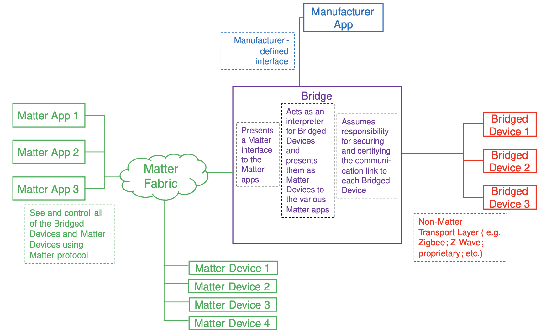
Figure 40. principle of bridging: the non-Matter devices are exposed as Bridged Devices to Nodes on the Fabric. The Matter Nodes can communicate with both the (native) Matter devices as well as the Bridged Devices (by virtue of the Bridge which performs the translation between Matter and the other protocol).
9.12.2. Exposing functionality and metadata of Bridged Devices
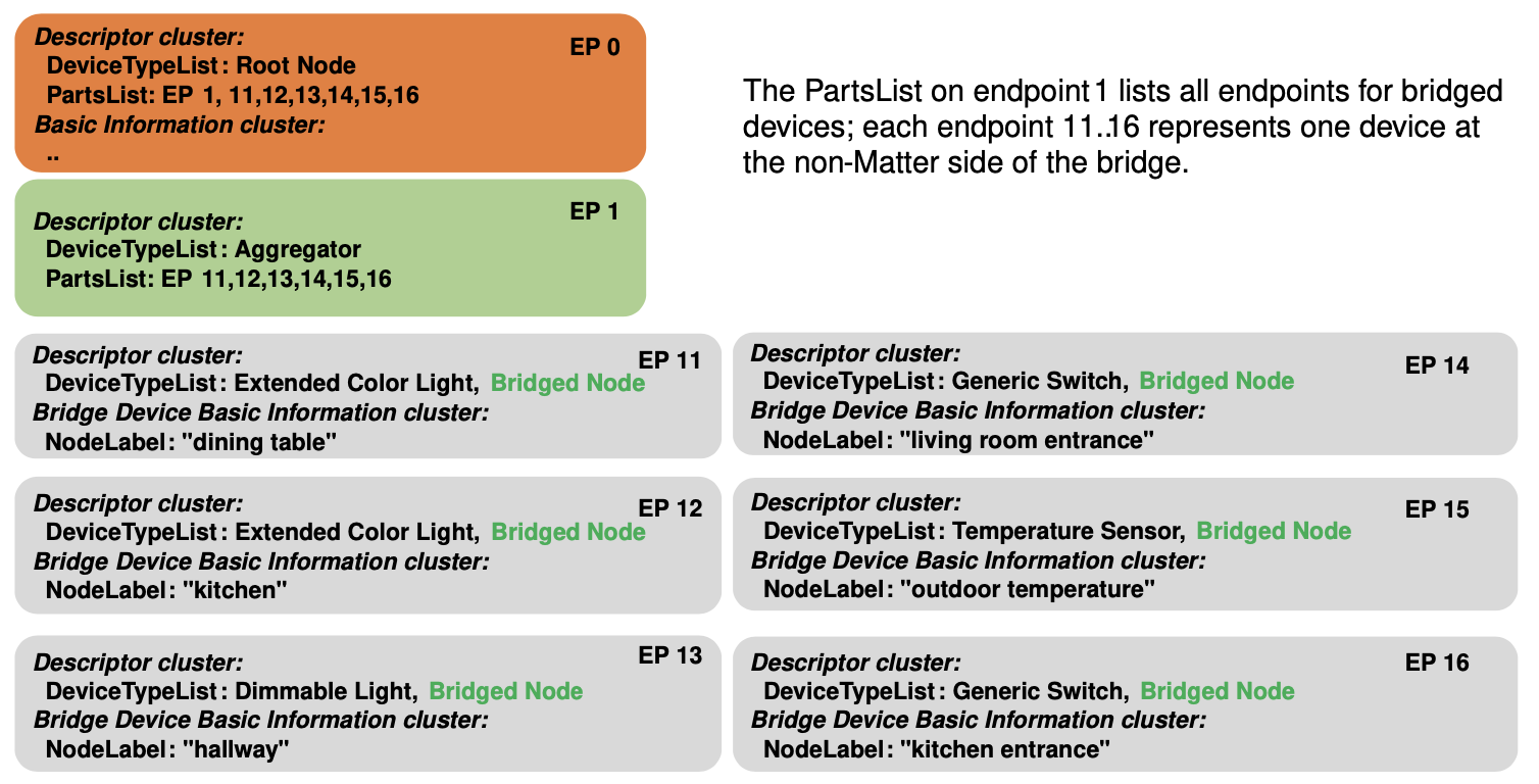
Figure 41. example of endpoints representing Bridged Devices
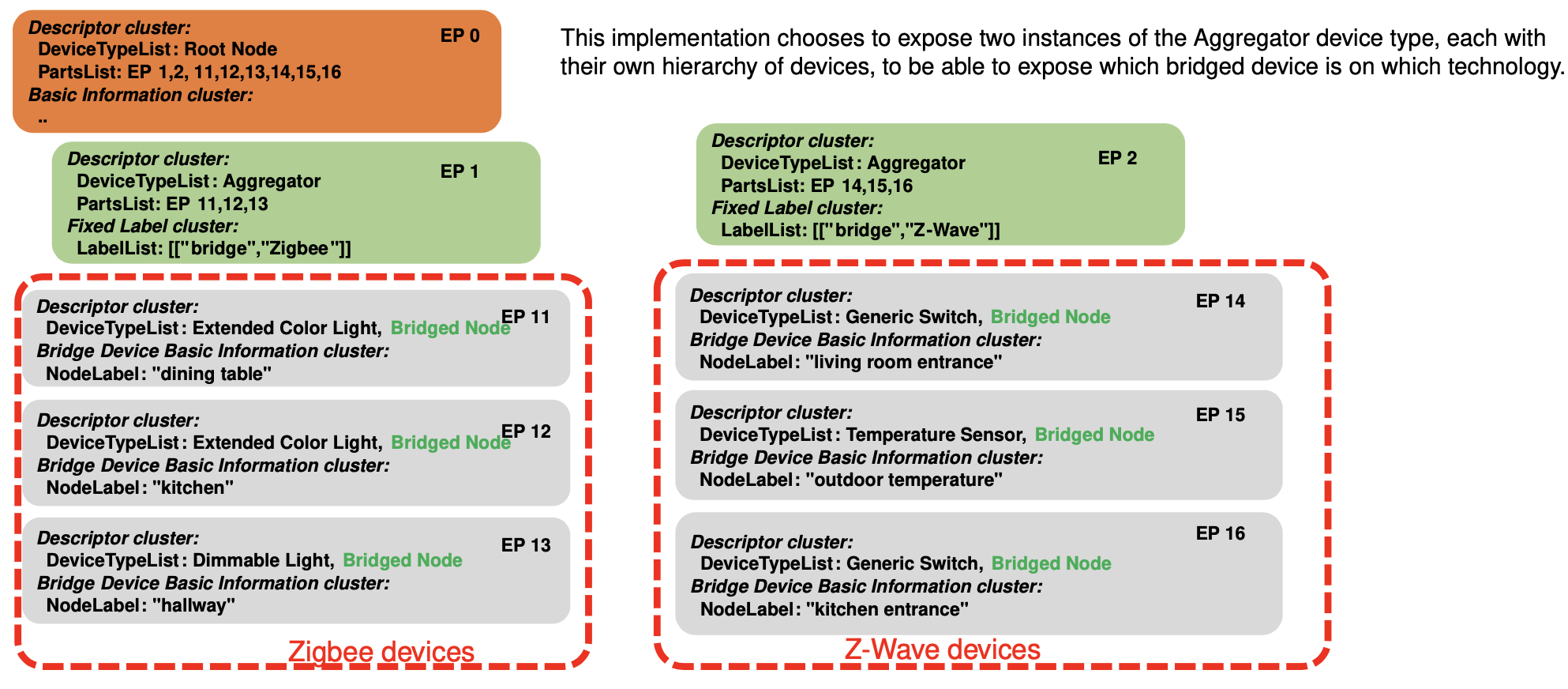
Figure 42. example of endpoints representing Bridged Devices from two technologies
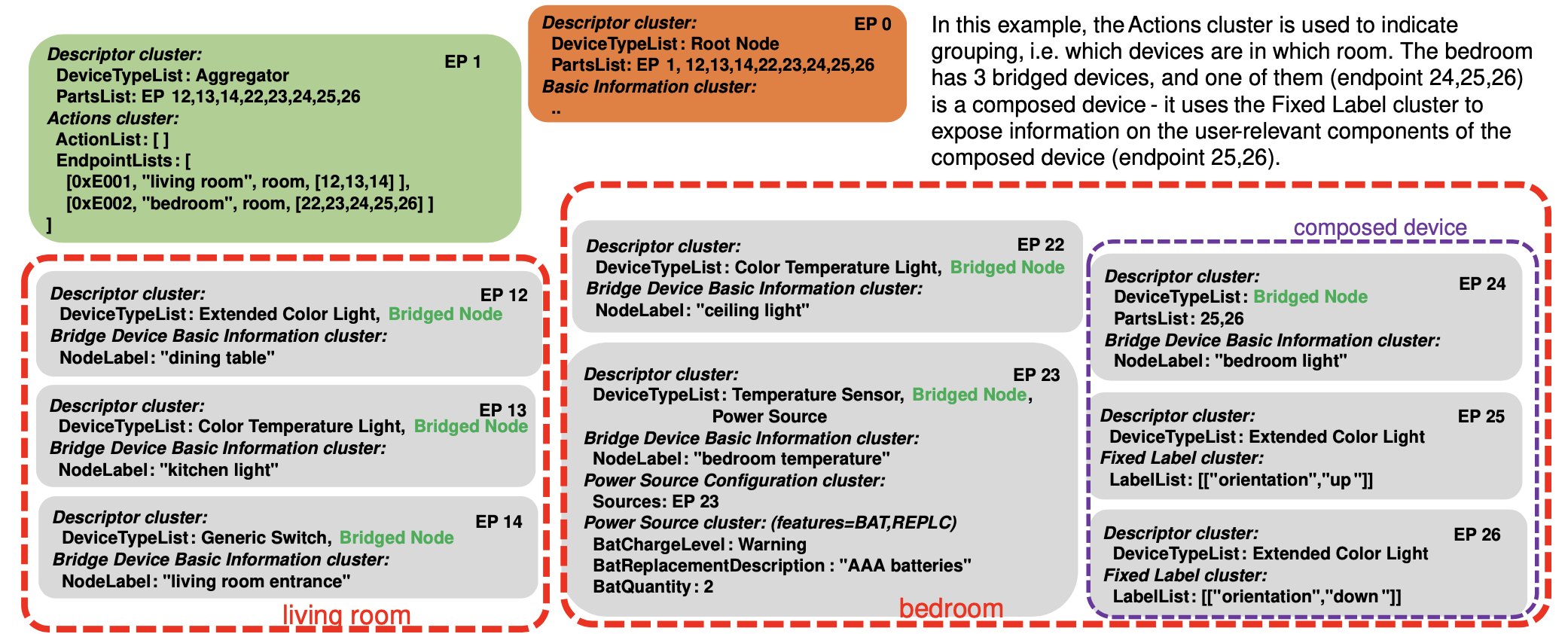
Figure 43. example of endpoints representing Bridged Devices using grouping
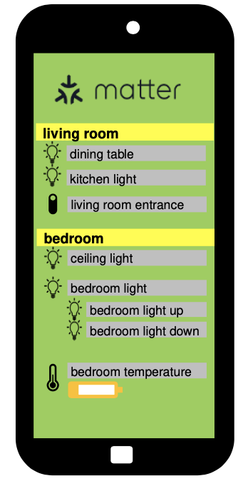
Figure 44. impression of app UI indicating information for the Bridged Devices
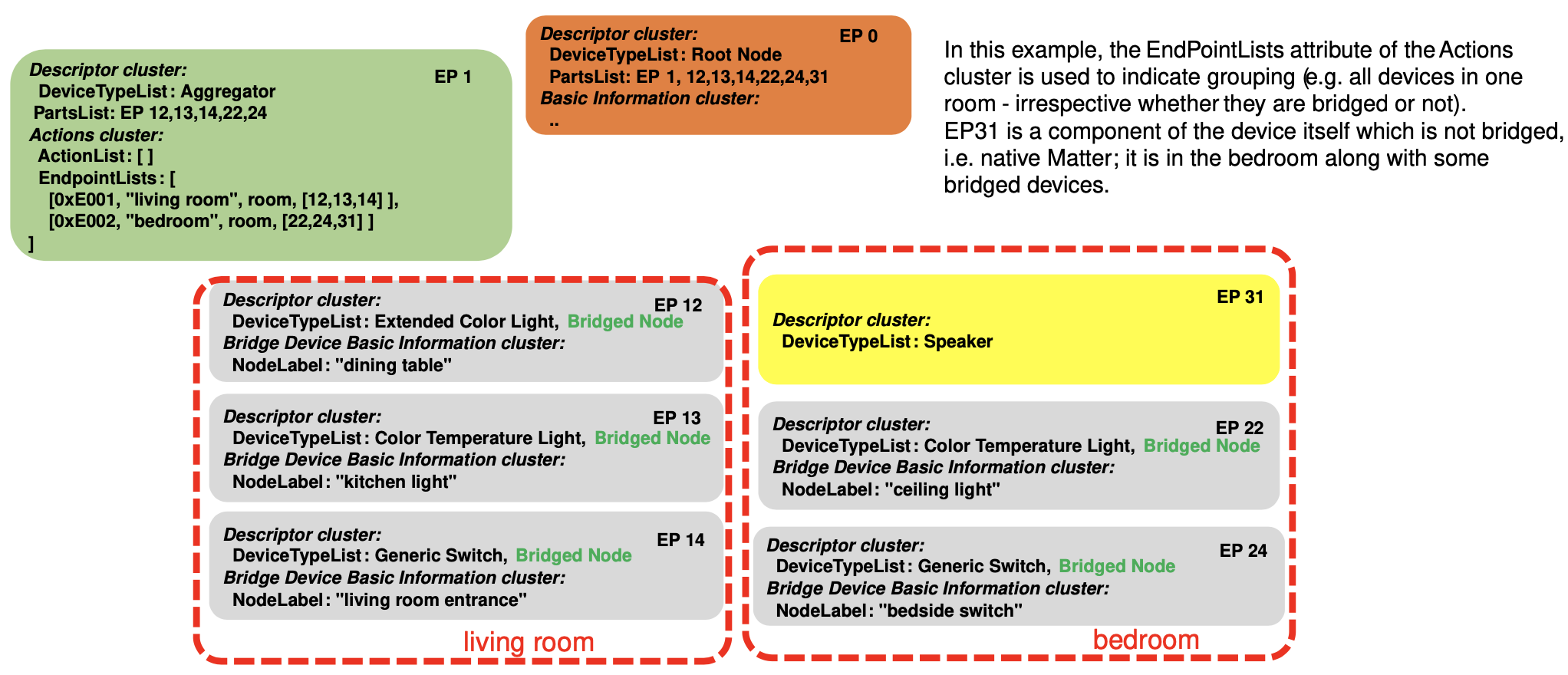
Figure 45. example of Bridge with native Matter functionality
9.12.3. Discovery of Bridged Devices
A Node which discovers another Node with device type Aggregator on one of its endpoints SHOULD walk the entire tree of endpoints via the PartsList attributes and endpoints to discover the list of Bridged Devices, including their device types and other attributes, as well as any native Matter functionality potentially present on the Node.
9.12.4. Configuration of Bridged Devices
For configuration of the discovered Bridged Devices, two basic archetypes are described in the following sections: one for actuators and o``ne for sensors/switches``.
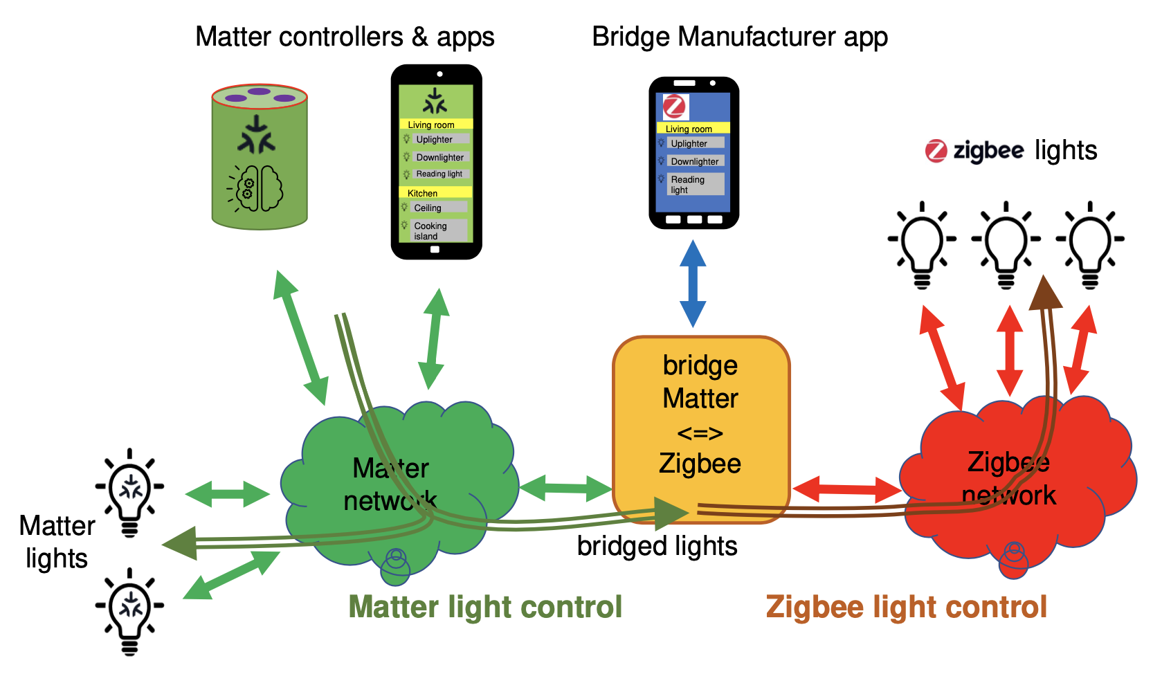
Figure 46. example of bridging lights
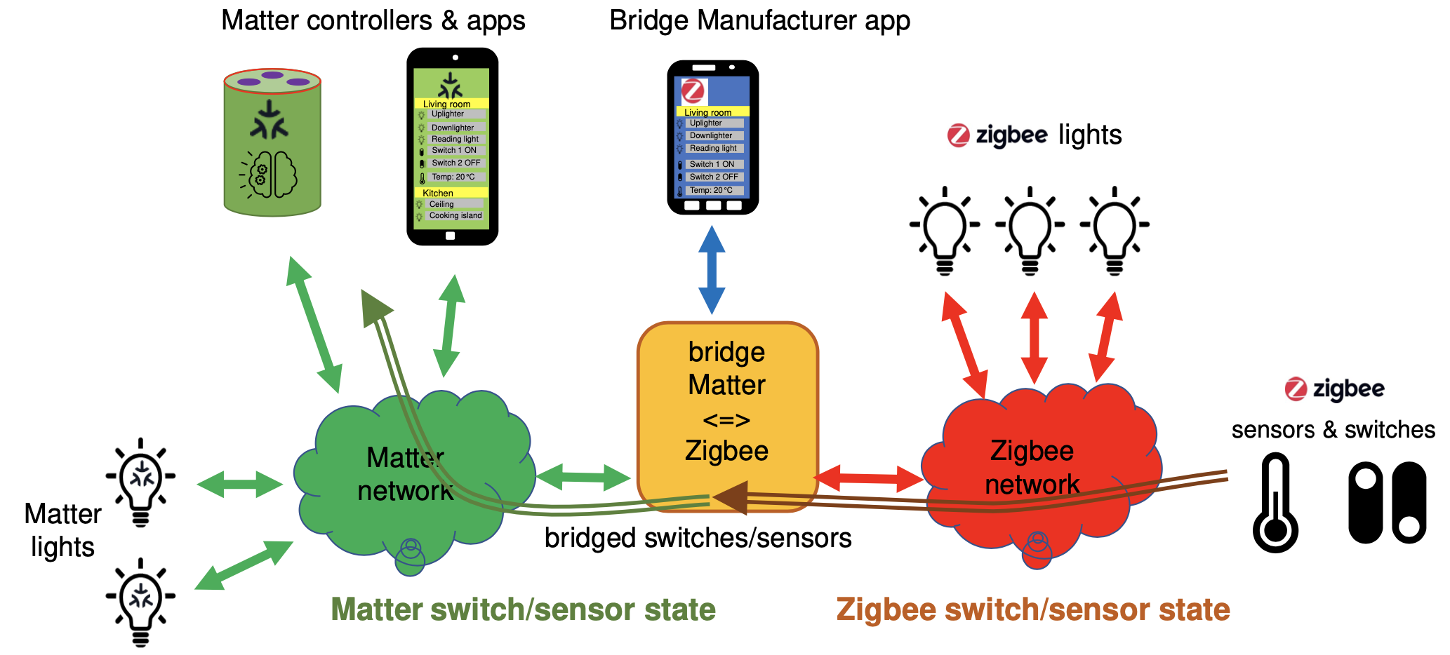
Figure 47. example of bridging switches and sensors
9.12.5. New features for Bridged Devices
Bridged Devices can have their software updated independently of the Bridge, through Bridge Manufacturer-specific means. These updates MAY result in one or more changes to their capabilities, such as supported clusters and/or attributes, for an endpoint.
9.12.6. Changes to the set of Bridged Devices
Bridged Devices can be added to or removed from the Bridge through Bridge-specific means. For example, the user can use a Manufacturer-provided app to add/remove Zigbee devices to/from their Matter-Zigbee Bridge.
9.12.7. Changes to device names and grouping of Bridged Devices
Typically, the user has some means (e.g. a Manufacturer-provided app) to assign names to the Bridged Devices, or names could be assigned automatically by the Bridge. The Bridge SHALL expose such names in the NodeLabel attribute of the Bridged Device Basic Information cluster on the applicable endpoint.
9.12.8. Setup flow for a Bridge (plus Bridged Devices)
As described above, the Bridge together with its Bridged Devices is exposed as a single Node with a list of endpoints.
9.12.9. Access Control
The Bridge is a Matter node, therefore it has a single Access Control Cluster for the entire Node, like every other Matter Node.
9.12.10. Software update (OTA)
The Bridge is a Matter device and its Matter-related functionality MAY be updated using the mechanism described in
Section 11.19, “Over-the-Air (OTA) Software Update”.The Bridged Devices, on the other hand, are not native Matter devices, do not have a Product ID, and are not listed in the Distributed Compliance Ledger. They are typically updated using a mechanism defined and deployed by the Bridge Manufacturer.
9.12.11. Best practices for Bridge Manufacturers
This section summarizes (in order of priority) the process to determine which non-Matter devices the Bridge exposes to the Fabric.
9.12.12. Best practices for Administrators
An Administrator MAY indicate to users which devices are native Matter and which ones are Bridged Devices, as determined using the presence of a Bridged Node device type on the endpoint, in order to ensure the user does not make assumptions about the Bridged Devices having the same security requirements as native Matter devices.
9.13. Bridged Device Basic Information Cluster
This Cluster serves two purposes towards a Node communicating with a Bridge:
• indicate that the functionality on the Endpoint
where it is placed (and its Parts) is bridged from a non-Matter technology
• provide a centralized collection of attributes that
the Node MAY collect to aid in conveying information
regarding the Bridged Device to a user,
such as the vendor name, the model name, or user-assigned name.
This cluster has been derived from the
Basic Information Cluster, and provides generic information about the Bridged Device.
Attributes:
Name |
Conformance |
|---|---|
DataModelRevision |
X |
VendorName |
O |
VendorID |
O |
ProductName |
O |
ProductID |
X |
NodeLabel |
O |
Location |
X |
HardwareVersion |
O |
HardwareVersionString |
O |
SoftwareVersion |
O |
SoftwareVersionString |
O |
ManufacturingDate |
O |
PartNumber |
O |
ProductURL |
O |
ProductLabel |
O |
SerialNumber |
O |
LocalConfigDisabled |
X |
Reachable |
M |
UniqueID |
O |
CapabilityMinima |
X |
Events:
Name |
Conformance |
|---|---|
StartUp |
O |
ShutDown |
O |
Leave |
O |
ReachableChanged |
M |
9.14. Actions Cluster
This cluster provides a standardized way for a Node (typically a Bridge, but could be any Node) to expose:
• information about logical grouping of endpoints on the Node (example: lights in a room)
• information about named actions that can be performed on such a group of endpoints
(example: recall a scene for a group of lights by its name)
• commands to trigger such actions
• events to receive feedback on the state of such actions.
Attributes:
0x0000 ActionList list[ActionStruct]
0x0001 EndpointLists list[EndpointListStruct]
0x0002 SetupURL string
Commands:
0x00 InstantAction client ⇒ server
0x01 InstantActionWithTransition client ⇒ server
0x02 StartAction client ⇒ server
0x03 StartActionWithDuration client ⇒ server
0x04 StopAction client ⇒ server
0x05 PauseAction client ⇒ server
0x06 PauseActionWithDuration client ⇒ server
0x07 ResumeAction client ⇒ server
0x08 EnableAction client ⇒ server
0x09 EnableActionWithDuration client ⇒ server
0x0a DisableAction client ⇒ server
0x0b DisableActionWithDuration client ⇒ server
Events:
0 StateChanged INFO
1 ActionFailed INFO
Data Types:
0 ActionID uint16
1 Name string
2 Type ActionTypeEnum
3 EndpointListID uint16
4 SupportedCommands map16
5 State ActionStateEnum
9.14.10. Examples
9.14.10.1. Example 1: Scene recall
User has defined a scene on a number of lights. The corresponding action would have these data fields describing it:
• Name="sunset"
• Type=scene
• EndpointListID references a struct referencing the set of involved endpoints
◦ Name="living room"
◦ Type=room
◦ Endpoints=list of the endpoints of the lights in this room
• SupportedCommands: `InstantAction`, `InstantActionWithTransition`
The
InstantActioncommand (e.g. triggered by a voice command “set sunset in living room”) will trigger the server to activate that scene on those lights.When a slow fade-in is preferred, the
InstantActionWithTransitioncan be used, with a TransitionTime parameter of e.g. 50 (denoting 5 s).
Figure 48. State diagram for example ‘scene recall’
9.14.10.2. Example 2: Set dynamic light effect
SupportedCommands:
StartAction,StartActionWithDuration,StopActionType=scene
The
StartActionWithDurationcommand (e.g. triggered by a voice command “play sunset in living room for 1 hour”) will trigger the server to activate a dynamic pattern with colors inspired by sunset on the associated lights.At any time, the
StopActioncan be used to stop the effect.
Figure 49. State diagram for example ‘dynamic light effect’
9.14.10.3. Example 3: Pause sensor automation
Name=”motion sensor”
Type=automation
SupportedCommands:
EnableAction,DisableAction,PauseAction,PauseActionWithDuration,ResumeActionTypically, without a Matter command the action’s state would be ‘Active’.
The
PauseActionWithDurationcommand (e.g. triggered by a voice command “disable the motion sensor in living room for 2 hours”) will trigger the server to disable the behavior associated with the motion sensor for the specified time.A
ResumeActioncommand would make this behavior active again.
Figure 50. State diagram for example ‘pause sensor automation’
9.14.10.4. Example 4: Wake-up routine
Name=”wakeup”
Type=sequence
SupportedCommands:
EnableAction,DisableAction,DisableActionWithDuration,PauseAction,PauseActionWithDuration
User has defined a wake-up routine: the lights in the bedroom will gradually become brighter and change in color temperature to simulate a sunrise. The sequence lasts for e.g. 30 minutes. Near the end of the sequence, the window coverings would be (partially) opened as well.
Figure 51. State diagram for example ‘wake-up experience’
9.14.10.5. Example 5: Scheduled scene recall
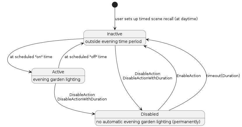
Figure 52. State diagram for example ‘scheduled scene recall’
9.14.10.6. Example 6: Alarm system
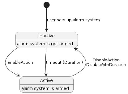
Figure 53. State diagram for example ‘alarm system’
9.15. Proxy Architecture
9.15.1. Motivation
Constrained devices might not support more than a handful of subscriptions.
This is usually attributable to a limited memory or battery.
However, there might be a large number of clients who desire to subscribe to that device.
9.15.2. Subscription Proxy: Overview
A subscription proxy is a type of Node that is capable of multiplexing subscriptions from multiple subscribers onto a single subscription to a given publisher.
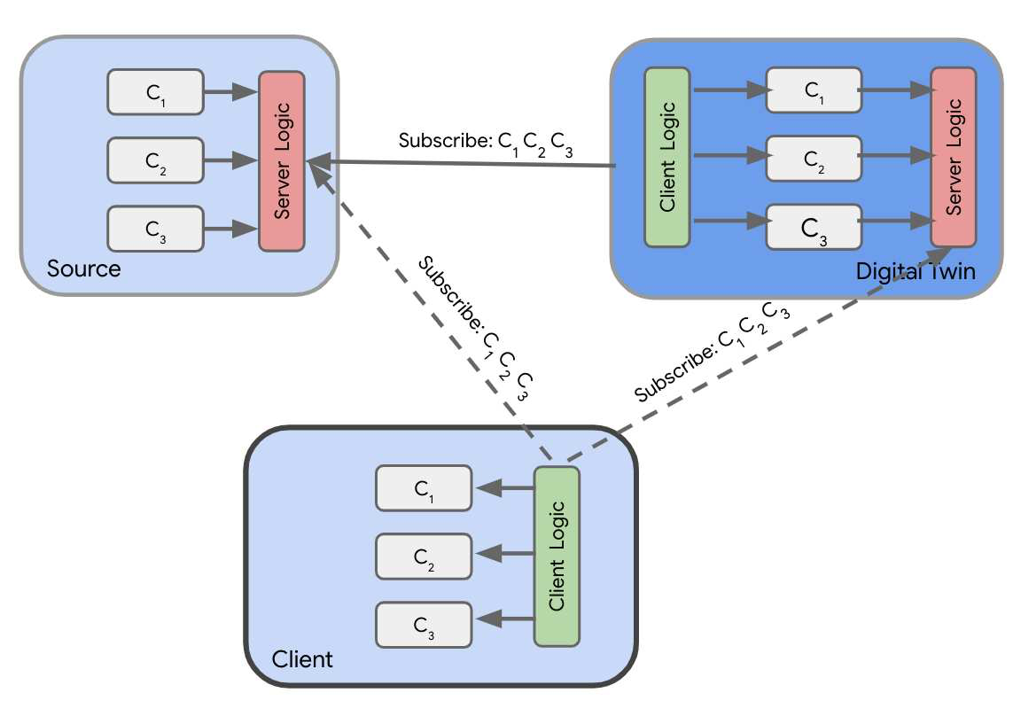
Figure 54. Digital twin acting as a proxy re-publishing clusters
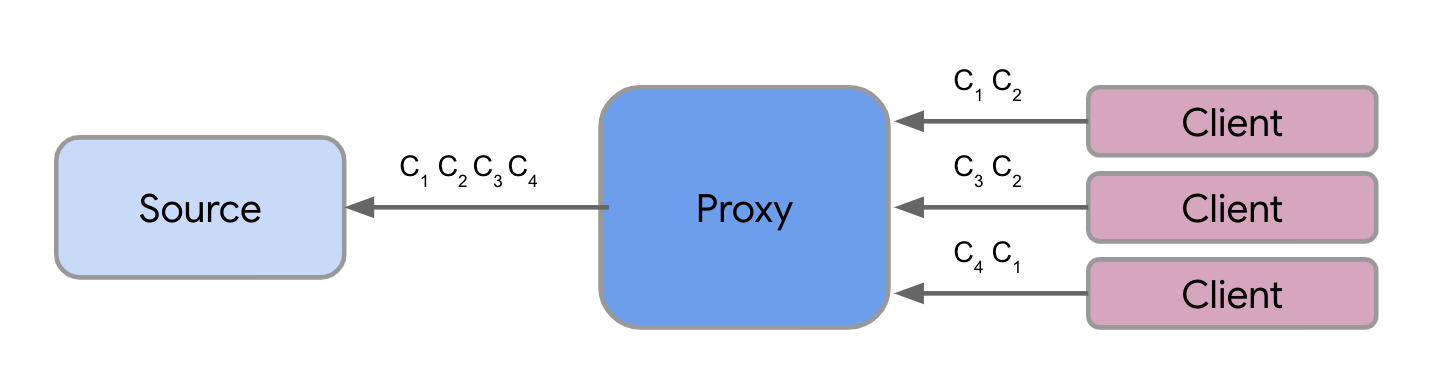
Figure 55. Proxy multiplexing interest sets from 3 distinct clients
A proxy SHALL only proxy subscribe interactions. It SHALL NOT proxy any other type of interaction.
9.15.3. Composition & Paths
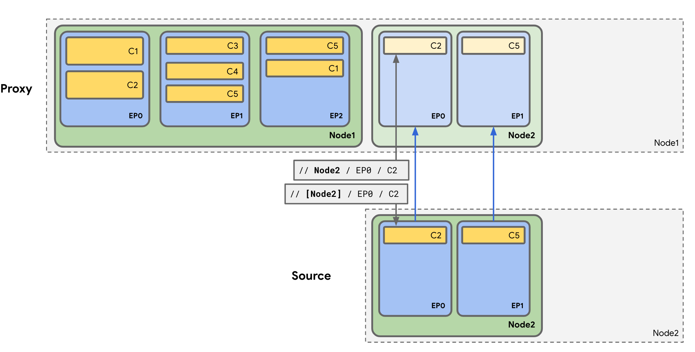
Figure 56. Sample paths when subscribing to a proxy vs the source
A client subscribing to a proxy SHALL specify the Node ID of the source it wishes to subscribe to in the Path. This SHALL be different from the logical destination Node ID of the message, which SHALL be the Node ID of the proxy.
9.15.4. Proxy Subscriptions
The term
'upstream subscription'refers to the subscription from the proxy either directly to the source, or indirectly to another proxy for that source’s data.The term
'downstream subscription'refers to the subscription from either a client or another proxy to the proxy in question.
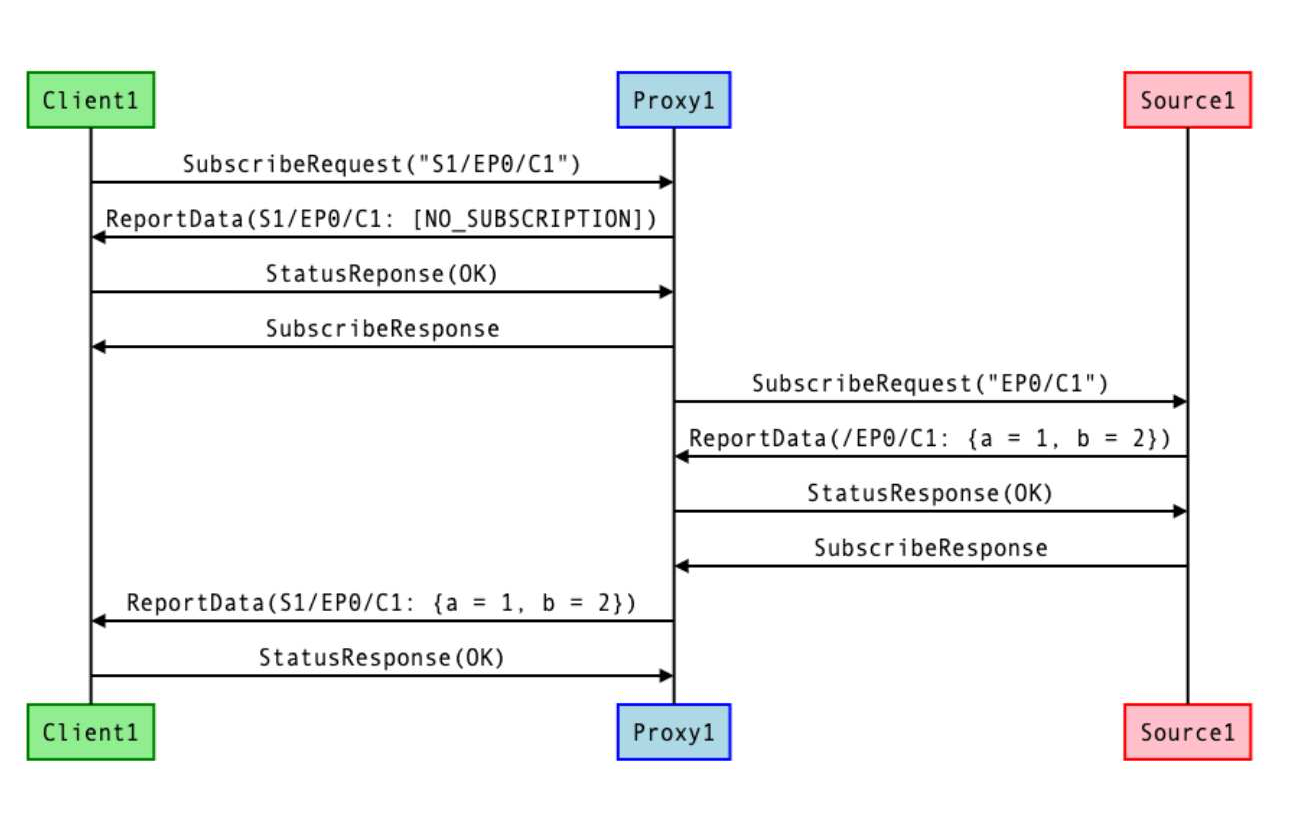
Figure 57. Upstream/Downstream subscription sequences
9.15.5. Schemas and Data Serialization/Deserialization
Unlike clients that need to semantically interpret data in addition to deserializing/serializing to/from its internal data stores, a proxy only needs to do the latter.
9.15.6. Indirect Proxies
A proxy MAY subscribe to another proxy instead of subscribing directly to the source. This creates proxy chains that allow a single source to be proxied by multiple proxies, allowing better use of available proxy capacity.
9.15.7. Proxy Discovery & Assignment Flow
The following flow describes the process by which a client:
• Discovers that a source needs a proxy
• Finds an appropriate proxy on the network that is able to handle its request
• Sets up the proxy to subscribe to the source
9.15.7.1. Step 0: Proxy Setup
A device indicates its ability to act as a certified proxy through stating support for the
Subscription Proxydevice type.When such a device is commissioned, the commissioner SHALL recognize this ability and MAY write the NodeIds of all the sources that need proxying into the
Proxy Configuration Clusteron the proxy device. Alternatively, it MAY configure the proxy to wildcard proxy all devices, removing the need to specify a particular set of NodeIds.Additionally, the commissioner MAY write the Node ID of the newly added proxy to the
Valid Proxies Clusteron source devices that needs proxying. This cluster stores the static list of candidate proxies for a given device. Only devices that support the cluster would need to have this configuration written.
9.15.7.2. Step 1: Rejection
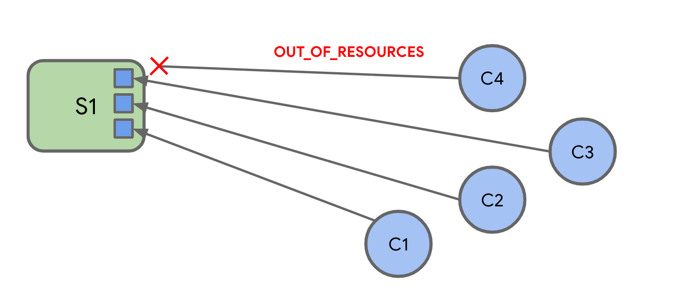
Figure 58. Rejection: The constraints of the source have been simplified down to having 3 available subscription slots that get filled up.When a client tries to subscribe to the source and is sent back a StatusResponse containing a RESOURCE_EXHAUSTED IM status code
9.15.7.3. Step 2: Proxy Discovery
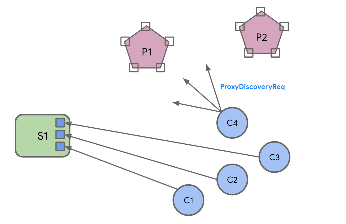
Figure 59. Discovery Request
The client sends out a
Proxy Discover Request Commandas a groupcast message to theAll Proxiesuniversal group.The client SHALL momentarily subscribe to the IPv6 address that maps to the All Proxies universal group to appropriately receive all responses.
9.15.7.4. Step 3: Proxy Response
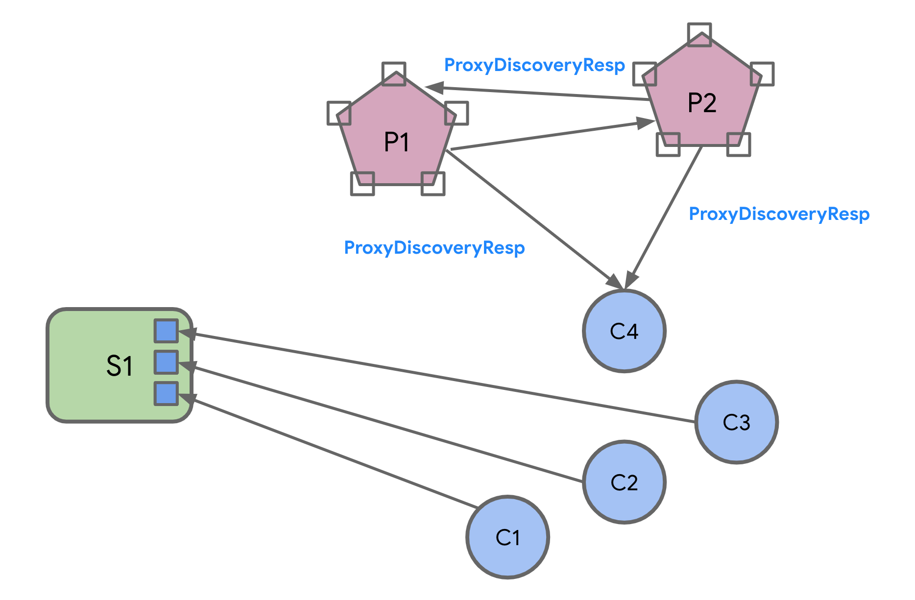
Figure 60. Proxies send back responses
Proxies respond to the request with a Proxy Discover Response Command sent as a groupcast message to the All Proxies universal group.
A proxy SHALL only send this message when it can handle the subscription request
The response will contain metadata about its ability to handle the subscription.
The
Proxy Discover Response CommandSHALL be sent as a completely separate, un-related transaction to the original request.The client SHALL correlate the two using the
SourceNodeIdpresent in both messages.Proxies SHALL stagger their responses by waiting for a random interval between 0 and
PROXY_SCAN_RESPONSE_JITTERbefore sending theProxy Discover Response Commandto prevent overwhelming the network or the client, which can be constrained and can have limited buffers.
9.15.7.5. Step 4: Proxy Selection
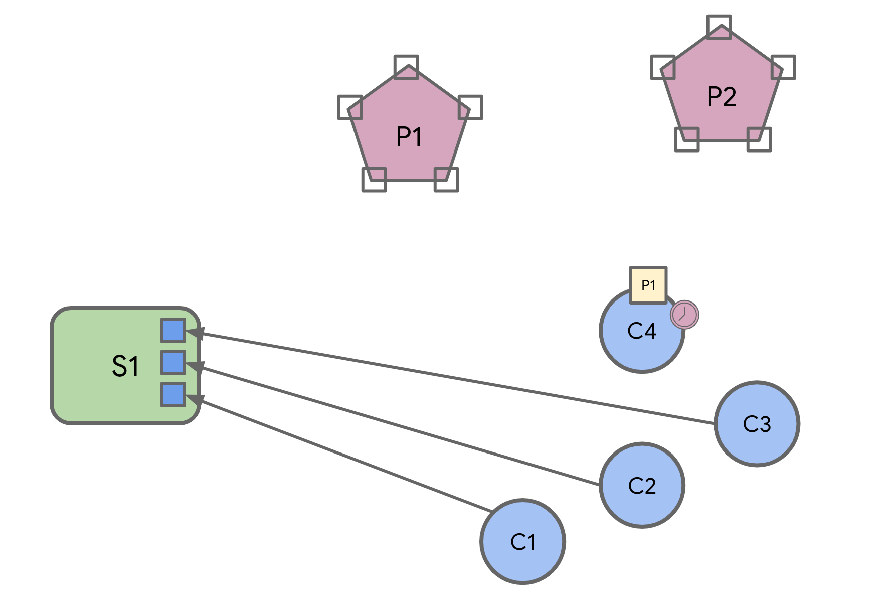
Figure 61. Selecting a Proxy
Client SHALL wait for
PROXY_SCAN_PERIODto aggregate all responses and SHALL filter the set of responses received.Clients MAY unsubscribe from the IPv6 multicast group that maps to the All Proxies universal group after aggregating the responses.
9.15.7.6. Step 5: Proxy Subscription
The client then subscribes to the proxy it has selected.
The proxy will do one of two things:
- Option 1
If there isn’t another proxy already subscribed to the source
- Option 2
If there is already another proxy subscribed to that source
Option 1
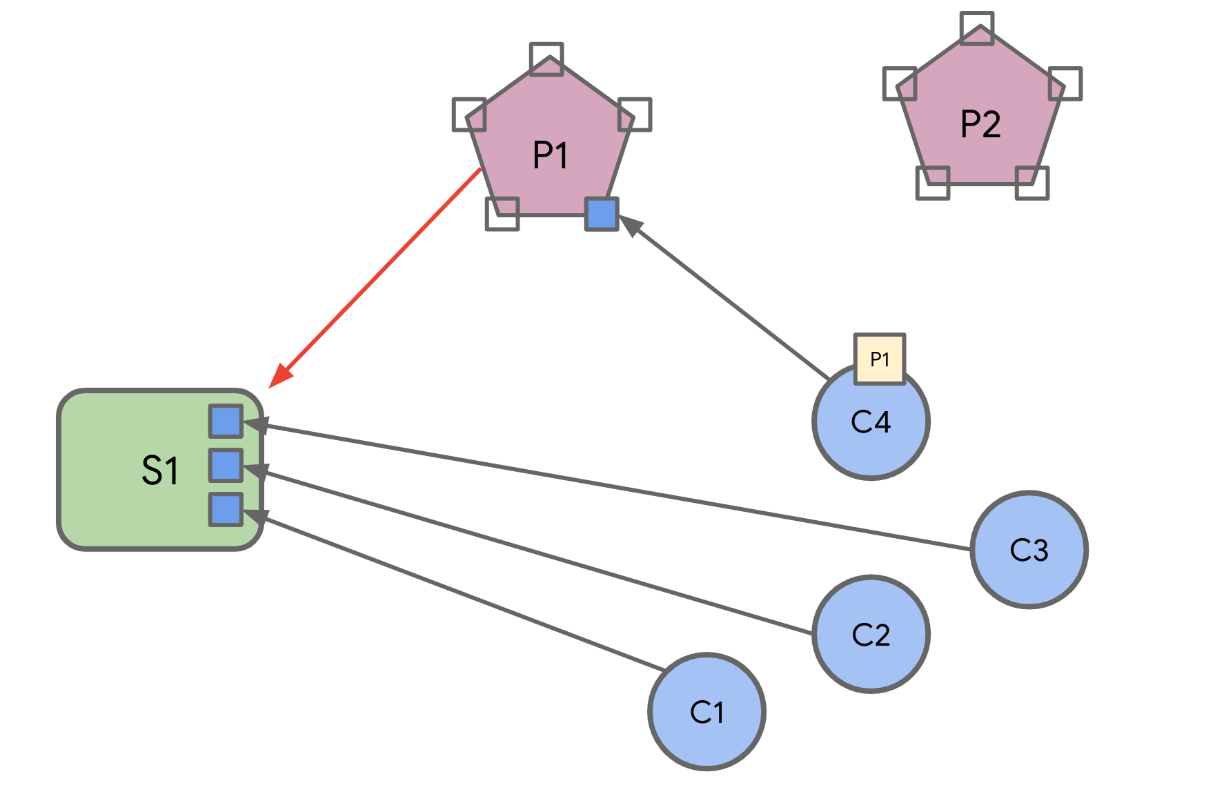
Figure 62. Primary proxy subscription
If there isn’t another proxy already subscribed to the source, the proxy subscribes to the source directly
Option 2
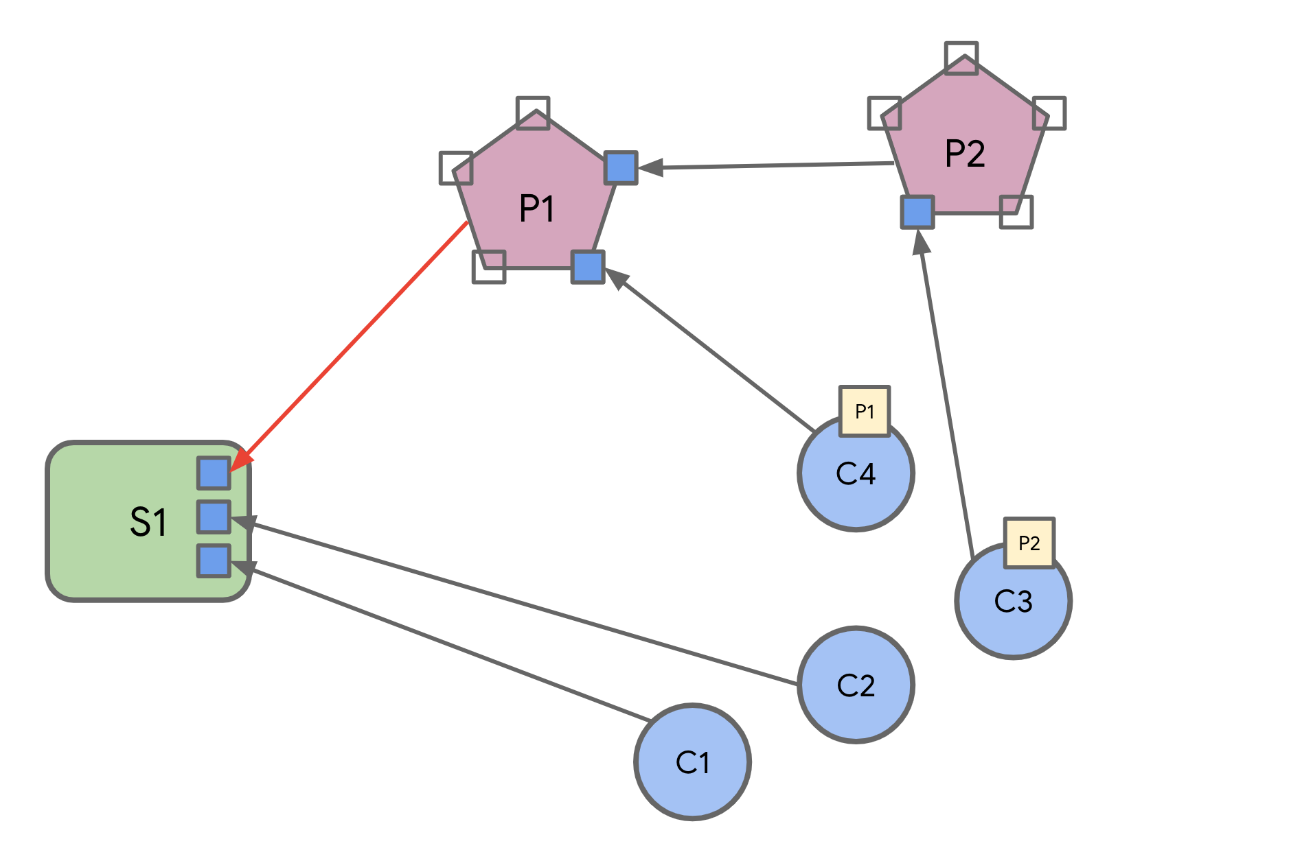
Figure 63. Primary proxy subscription
If there is already another proxy subscribed to that source, the selected proxy subscribes to that proxy instead.
9.15.7.7. Step 6: Eviction
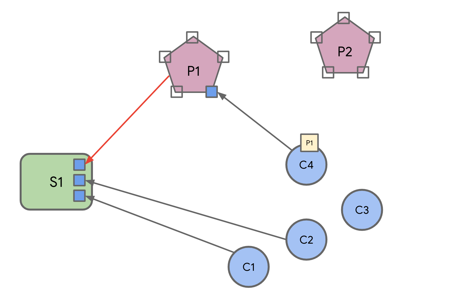
Figure 64. C3 gets evicted
At this point, the source might not be able to handle another subscription. If so, it SHALL evict non- proxy subscriptions to make space for the proxy subscription.
9.15.7.8. Step 7: Re-Assignment
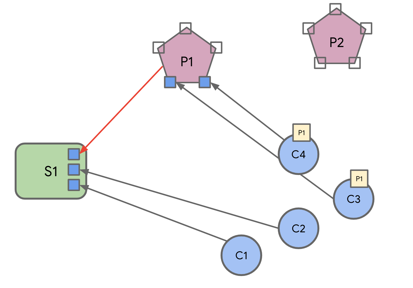
Figure 65. C3 gets reassigned to P1
The evicted clients undergo the same proxy discovery/selection process, and eventually settle on a set of proxies.
9.15.7.9. Notable Characteristics
The system ‘auto-balances’ based on the needs of clients and the capabilities of the source
No persistent state or a priori configuration is needed on any node
No a priori heuristics are needed to figure out if a node should be proxied.
Robust to proxy failure by leveraging the liveness construct of subscriptions to accelerate discovery
No centralized proxy management/assignment service is needed. There is no single point of failure. No need for an election, state backup, or fail-over.
Low complexity on server (which are usually the more constrained device), slightly more on the client
9.15.8. Constraints
A source SHALL NOT evict an existing proxy already subscribed to it
There SHOULD only be one proxy node directly subscribed to a source in a single-fabric setting
9.15.9. Certification
To ensure a consistent expectation of behavior from a proxy device, the proxy SHOULD be certified by the Connectivity Standards Alliance against the expectations of a proxy. Once certified, it MAY claim compatibility against the Subscription Proxy device type.
9.15.10. Security & Privacy
To prevent malicious or unattested devices from acting as proxies to clients, the Valid Proxies Cluster provides a scheme for admins to specify the NodeIds of valid, attested proxies to the source itself, which is in turn conveyed to clients. This allows for filtering of the ensuing Proxy Discover Response Command messages to only select valid, trusted proxies.
9.15.11. Parameters and Constants
Table 83. Glossary of constants:
PROXY_SCAN_RESPONSE_JITTER:
Default Value: 1000 milliseconds
The maximum amount of time to randomly wait
before sending a `Proxy Discover Response Command` message.
PROXY_SCAN_PERIOD:
Default Value: 1100 milliseconds
The maximum amount of time `initiator of proxy discovery` will wait
to collect `Proxy Discover Response Command` messages
after sending a `Proxy Discover Request Command` message.
9.15.12. Clusters
9.15.13. Proxy Discovery Cluster
This cluster contains commands needed to do proxy discovery as defined in the Section 9.15.7.3, “Step 2: Proxy Discovery” and Section 9.15.7.4, “Step 3: Proxy Response”
Commands:
0x00 ProxyDiscoverRequest Client ⇒ Server
0x01 ProxyDiscoverResponse Server ⇒ Client
9.15.14. Proxy Configuration Cluster
This cluster provides a means for a proxy-capable device to be told the set of Nodes it SHALL proxy.
Cluster Identifiers:
0x0042 ProxyConfiguration
9.15.15. Valid Proxies Cluster
This cluster provides a means for a device to be told of the valid set of possible proxies that can proxy subscriptions on its behalf as per Section 9.15.7, “Proxy Discovery & Assignment Flow”.
Cluster Identifiers:
0x0044 ValidProxies
Commands:
0x00 Get Valid Proxies Request Client ⇒ Server
0x01 GetValidProxiesResponse Server ⇒ Client
Chapter 10. Interaction Model Encoding Specification
10.1. Overview
This specification details the encoding of the
Interaction Model (IM)in the Matter TLV format.Specifically, it details the encoding of the application payload for Matter messages that map to the Interaction Model.
10.2. Messages
10.2.1. IM Protocol Messages
• Vendor ID = 0x0000 (Matter Common)
• Protocol ID = PROTOCOL_ID_INTERACTION_MODEL
Protocol Opcode |
Action |
Message |
|---|---|---|
0x01 |
Status Response |
StatusResponseMessage |
0x02 |
Read Request |
ReadRequestMessage |
0x03 |
Subscribe Request |
SubscribeRequestMessage |
0x04 |
Subscribe Response |
SubscribeResponseMessage |
0x05 |
Report Data |
ReportDataMessage |
0x06 |
Write Request |
WriteRequestMessage |
0x07 |
Write Response |
WriteResponseMessage |
0x08 |
Invoke Request |
InvokeRequestMessage |
0x09 |
Invoke Response |
InvokeResponseMessage |
0x0A |
Timed Request |
TimedRequestMessage |
10.2.2. Common Action Information Encoding
Message Header Encoded Action Information:
• Message Exchange ID
• Source Node ID
• Destination ID
• Protocol ID
• Protocol OpCode
10.2.3. Chunking
Chunking is the act of splitting an Action that contains attribute/event data, specifically ReportData and WriteRequest actions, into multiple messages at logical boundaries due to the size limitations imposed by IPv6 for UDP packets
10.2.4. Transaction Flows
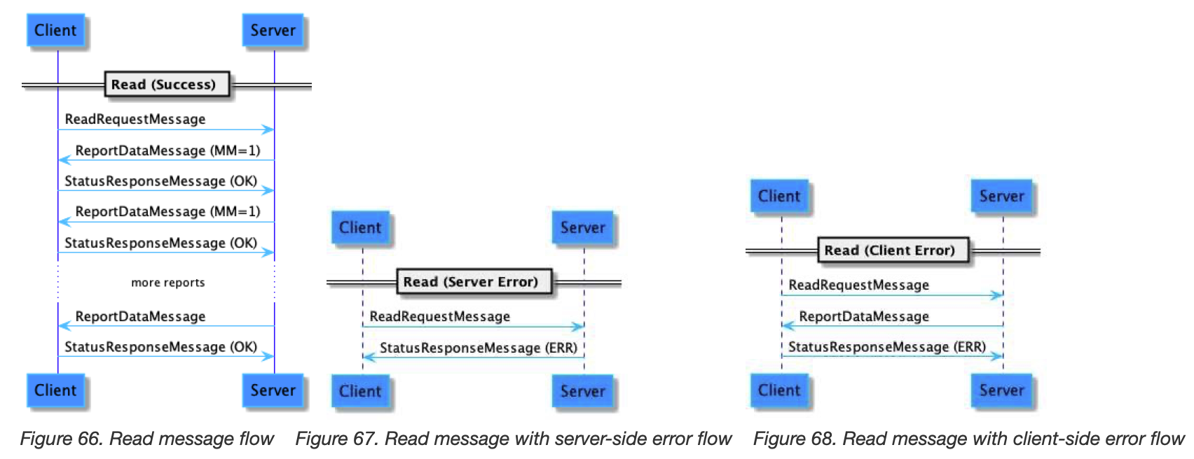
Figure 66. Read message flow
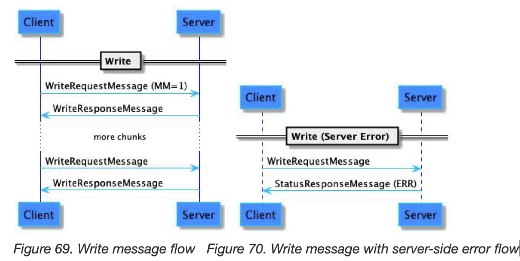
Figure 69. Write message flow
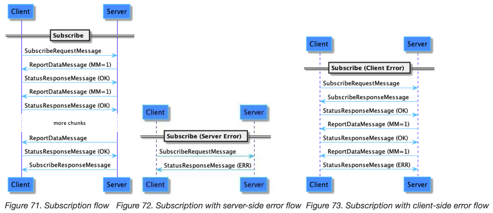
Figure 71. Subscription flow
10.3. Data Types
The IM specification defines a number of schema data types that are usable in a given cluster schema definition.
Base Data Types:
• Discrete
◦ enum
◦ data
◦ map
◦ boolean
• Analog
◦ uint
◦ int
◦ float32
◦ float64
• Composite
◦ String
◦ octstr
• Collection
◦ list
◦ struct
10.4. Sample Cluster
This section defines a sample cluster (with attributes, events, and commands) for illustrative purposes; it SHALL NOT be interpreted as a real cluster.
10.5. Information Blocks
10.5.1. Tag Rules
Unless otherwise noted, all context tags SHALL be emitted in the order as defined in the appropriate specification. This is done to reduce receiver side complexity in having to deal with arbitrary order tags.
10.5.2. AttributePathIB
Examples:
• Select all attributes on a given cluster and endpoint:
AttributePath = [[ Endpoint = 10, Cluster = Disco Ball ]]
• Select all attributes in all clusters on a given endpoint:
Path = [[ Endpoint = 10 ]]
• Select all attributes in all clusters on the node:
Path = [[ ]]
10.5.3. DataVersionFilterIB
10.5.4. AttributeDataIB
Examples:
Update a top-level attribute:
AttributeDataIB = {
DataVersion = 1,
Path = [[ Endpoint = 10, Cluster = Disco Ball, FieldID = Axis ]],
Data = 90
}
Collection Types (List)
Modify a list item:
AttributeDataIB = {
DataVersion = 1,
Path = [[ Endpoint = 10, Cluster = Disco Ball, FieldID = Pattern, ListIndex = 1]],
Data = {
Duration = 900,
Rotate = Clockwise, // On the wire enum value (1) is used
Speed = 12,
Axis = 0,
// WobbleSpeed omitted; this cluster instance does not support Wobble
Passcode = "1234"
}
}
Add an item to a list:
AttributeDataIB = {
DataVersion = 1,
Path = [[ Endpoint = 10, Cluster = Disco Ball, FieldID = Pattern, ListIndex =null]],
Data = {
Duration = 100,
Rotate = Counterclockwise, // On the wire enum value (2) is used
Speed = 12,
Axis = 90,
// WobbleSpeed omitted; this cluster instance does not support Wobble
Passcode = "9876"
}
}
Delete an item in a list:
AttributeDataIB = {
DataVersion = 1,
Path = [[ Endpoint = 10, Cluster = Disco Ball, FieldID = Pattern, ListIndex = 0]],
Data = null,
}
Replace a list (Single IB):
AttributeDataIB = {
DataVersion = 1,
Path = [[ Endpoint = 10, Cluster = Disco Ball, FieldID = Pattern]],
Data = [[
{
Duration = 900,
Rotate = Clockwise, // On the wire enum value (1) is used
Speed = 12,
Axis = 0,
// WobbleSpeed omitted; this cluster instance does not support Wobble
Passcode = "1234"
} {
Duration = 100,
Rotate = Counterclockwise, // On the wire enum value (2) is used
Speed = 12,
Axis = 90,
// WobbleSpeed omitted; this cluster instance does not support Wobble
Passcode = "9876"
},
]]
}
Replace a list (Multiple IBs):
AttributeDataIB1 = {
DataVersion = 1,
Path = [[ Endpoint = 10, Cluster = Disco Ball, FieldID = Pattern ]],
Data = []
}
AttributeDataIB2 = {
DataVersion = 1,
Path = [[ Endpoint = 10, Cluster = Disco Ball, FieldID = Pattern, ListIndex = 0]],
Data = {
Duration = 900,
Rotate = Clockwise, // On the wire enum value (1) is used
Speed = 12,
Axis = 0,
Passcode = "1234"
}
}
AttributeDataIB3 = {
DataVersion = 1,
Path = [[ Endpoint = 10, Cluster = Disco Ball, FieldID = Pattern, ListIndex = 1]],
Data = {
Duration = 100,
Rotate = Counterclockwise, // On the wire enum value (2) is used
Speed = 12,
Axis = 90,
Passcode = "9876"
}
}
10.5.5. AttributeReportIB
10.5.6. EventFilterIB
10.5.7. ClusterPathIB
10.5.8. EventPathIB
Examples:
• Select a particular event type:
Path = [[ Endpoint = 10, Cluster = Disco Ball, Event = Pattern Change ]]
• Select all events on a given cluster (used in Read/Subscribe requests):
Path = [[ Endpoint = 10, Cluster = Disco Ball ]]
• Select all events on a given cluster with urgency (used in Read/Subscribe requests):
Path = [[ Endpoint = 10, Cluster = Disco Ball, IsUrgent = true ]]
10.5.9. EventDataIB
Examples:
EventDataElement = {
Path = [[ Endpoint = 10, Cluster = Disco Ball, EventID = Started ]],
EventNumber = 1001,
Priority = INFO,
EpochTimestamp = 102340234293,
Data = {
// Started event contains no data
}
}
10.5.10. EventReportIB
10.5.11. CommandPathIB
Examples:
• Select a particular command:
Path = [[ Endpoint = 10, Cluster = Disco Ball, Command = Stop Request ]]
• Select a particular command (addressed to a group):
Path = [[ Cluster = Disco Ball, Command = Stop Request ]]
10.5.12. CommandDataIB
Request + Response:
RequestCommandElement = {
CommandPath = [[ Endpoint = 10, Cluster = Disco Ball, Command = Stats Request ]],
CommandData = {} // Empty CommandData MAY be encoded as an empty container
}
ResponseCommandElement = {
CommandPath = [[ Endpoint = 10, Cluster = Disco Ball, Command = Stats Response ]],
CommandData = {
LastRun = 100,
Patterns = 1
}
}
Empty request:
RequestCommandElement = {
CommandPath = [[ Endpoint = 10, Cluster = Disco Ball, Command = Stop Request ]]
// Empty CommandData MAY also be omitted entirely
}
// No cluster specific response is returned; a status is passed via Invoke Response at
the Interaction layer
10.5.13. InvokeResponseIB
10.5.14. CommandStatusIB
10.5.15. EventStatusIB
10.5.16. AttributeStatusIB
10.5.17. StatusIB
10.6. Message Definitions
This section contains message definitions that correspond to their equivalent actions in the Interaction Model Specification.
10.6.3. ReportDataMessage
Event list (highlighting compressions):
EventReports = [
{
Path = [[ Endpoint = 10, Cluster = Disco Ball, EventID = Started ]],
ImportanceLevel = INFO,
Number = 1001,
UTCTimestamp = 102340234293,
Data = {
},
},
{
Path = [[ EventID = PatternChange]], // same endpoint and cluster but different event type
DeltaUTCTimestamp = 1000,
Data = {
PrevPattern = null,
CurPattern = {
Duration = 900,
Rotate = Clockwise, // On the wire enum value (1) is used
Speed = 12,
Axis = 0,
// WobbleSpeed omitted; this cluster instance does not support Wobble
Passcode = "1234"
},
NextPattern = {
Duration = 100,
Rotate = Counterclockwise, // On the wire enum value (2) is used
Speed = 12,
Axis = 90,
// WobbleSpeed omitted; this cluster instance does not support Wobble
Passcode = "9876"
}
}
},
{
Path = [[ ]], // same path as the previous path
DeltaUTCTimestamp = 900000000,
Data = {
PrevPattern = {
Duration = 900,
Rotate = Clockwise,
Speed = 12,
Axis = 0,
Passcode = "1234"
},
CurPattern = {
Duration = 100,
Rotate = Counterclockwise,
Speed = 12,
Axis = 90,
Passcode = "9876"
},
NextPattern = null
}
}
]
Chapter 11. Service and Device Management
11.1. Basic Information Cluster
This cluster provides attributes and events for determining basic information about Nodes
Events:
0x00 StartUp CRITICAL
0x01 ShutDown CRITICAL
0x02 Leave INFO
0x03 ReachableChanged INFO
11.2. Group Key Management Cluster
The
Group Key Management clustermanages group keys for the node.The cluster is scoped to the node and is a singleton for the node.
This cluster maintains a list of groups supported by the node.
Each group list entry supports a single group, with a single group ID and single group key.
Duplicate groups are not allowed in the list.
Additions or removal of a group entry are performed via modifications of the list. Such modifications require Administer privilege.
Attributes:
0x0000 GroupKeyMap list[GroupKeyMapStruct]
0x0001 GroupTable list[GroupInfoMapStruct]
0x0002 MaxGroupsPerFabric uint16
0x0003 MaxGroupKeysPerFabric uint16
Data Types:
GroupKeyMapStruct:
1 GroupId group-id
2 GroupKeySetID uint16
GroupKeySetStruct:
0 GroupKeySetID uint16
1 GroupKeySecurityPolicy enum8
2 EpochKey0 octstr
3 EpochStartTime0 epoch-us
4 EpochKey1 octstr
5 EpochStartTime1 epoch-us
6 EpochKey2 octstr
7 EpochStartTime2 epoch-us
8 GroupKeyMulticastPolicy enum8
Commands:
0x00 KeySetWrite Client ⇒ Server
0x01 KeySetRead Client ⇒ Server
0x02 KeySetReadResponse Server ⇒ Client
0x03 KeySetRemove Client ⇒ Server
0x04 KeySetReadAllIndices Client ⇒ Server
0x05 KeySetReadAllIndicesResponse Server ⇒ Client
11.3. Localization Configuration Cluster
Nodes should be expected to be deployed to any and all regions of the world. These global regions may have differing common languages, units of measurements, and numerical formatting standards.
Attributes:
0x0000 ActiveLocale string
0x0001 SupportedLocales list[string]
11.4. Time Format Localization Cluster
These global regions may have differing preferences for how dates and times are conveyed.
Attributes:
0x0000 HourFormat HourFormat
0x0001 ActiveCalendarType CalendarType
0x0002 SupportedCalendarTypes list[CalendarType]
Data Types:
HourFormat:
0 12hr
1 24hr
CalendarType:
0 Buddhist
1 Chinese
2 Coptic
3 Ethiopian
...
11.5. Unit Localization Cluster
These global regions may have differing preferences for the units in which values are conveyed in communication to a user.
Attributes:
0x0000 TemperatureUnit TempUnit
Data Types:
TempUnit:
0 Fahrenheit
1 Celsius
2 Kelvin
11.6. Power Source Configuration Cluster
This cluster is used to describe the configuration and capabilities of a Device’s power system.
Attributes:
0x0000 Sources list[endpoint-no]
11.7. Power Source Cluster
This cluster is used to describe the configuration and capabilities of a physical power source that provides power to the Node.
In case the Node has multiple power sources, each is described by its own Power Source cluster.
11.7.4. Features
Bit |
Code |
Feature |
Description |
|---|---|---|---|
0 |
WIRED |
Wired |
A wired power source |
1 |
BAT |
Battery |
A battery power source |
2 |
RECHG |
Rechargeable |
A rechargeable battery power source (requires Battery feature) |
3 |
REPLC |
Replaceable |
A replaceable battery power source (requires Battery feature) |
11.7.5. Data Types
11.7.5.1. WiredFault
Table 89. WiredFault ENUM:
0 Unspecified
1 OverVoltage
2 UnderVoltage
11.7.5.2. BatFault
Table 90. BatFault ENUM:
0 Unspecified
1 OverTemp
2 UnderTemp
11.7.5.3. BatChargeFault
Table 91. BatChargeFault ENUM:
0 Unspecified
1 AmbientTooHot
2 AmbientTooCold
3 BatteryTooHot
4 BatteryTooCold
5 BatteryAbsent
6 BatteryOverVoltage
7 BatteryUnderVoltage
8 ChargerOverVoltage
9 ChargerUnderVoltage
10 SafetyTimeout
11.7.6. Server
Table 92. PowerSourceStatus ENUM:
0 Unspecified
1 Active
2 Standby
3 Unavailable
Table 93. WiredCurrentType ENUM:
0 AC
1 DC
Table 94. BatChargeLevel ENUM:
0 OK
1 Warning
2 Critical
Table 95. BatReplaceability ENUM:
0 Unspecified
1 NotReplaceable
2 UserReplaceable
3 FactoryReplaceable
11.7.6.1. Attributes
0x0000 Status PowerSourceStatus 0x0001 Order uint8 0x0002 Description string
0x0003 WiredAssessedInputVoltage uint32 0x0004 WiredAssessedInputFrequency uint16 0x0005 WiredCurrentType WiredCurrentType 0x0006 WiredAssessedCurrent uint32 0x0007 WiredNominalVoltage uint32 0x0008 WiredMaximumCurrent uint32 0x0009 WiredPresent bool 0x000a ActiveWiredFaults list[WiredFault]
0x000b BatVoltage uint32 0x000c BatPercentRemaining uint8 0x000d BatTimeRemaining uint32 0x000e BatChargeLevel BatChargeLevel 0x000f BatReplacementNeeded bool 0x0010 BatReplaceability BatReplaceability 0x0011 BatPresent bool 0x0012 ActiveBatFaults list[BatFault]
0x0013 BatReplacementDescription string 0x0014 BatCommonDesignation uint32 0x0015 BatANSIDesignation string 0x0016 BatIECDe signation string 0x0017 BatApprovedChemistry uint32 0x0018 BatCapacity uint32 0x0019 BatQuantity uint8 0x001a BatChargeState BatChargeState 0x001b BatTimeToFullCharge uint32 0x001c BatFunctionalWhileCharging bool 0x001d BatChargingCurrent uint32 0x001e ActiveBatChargeFaults list[BatChargeFault]
11.7.6.2. Events
Id |
Name |
Type |
|---|---|---|
0 |
WiredFaultChange |
WiredFaultChangeType |
1 |
BatFaultChange |
BatFaultChangeType |
2 |
BatChargeFaultChange |
BatChargeFaultChangeType |
Table 99. WiredFaultChangeType Struct:
0 Current list[WiredFault]
1 Previous list[WiredFault]
Table 100. BatFaultChangeType Struct:
0 Current list[BatFault]
1 Previous list[BatFault]
Table 101. BatChargeFaultChangeType Struct:
0 Current list[BatChargeFault]
1 Previous list[BatChargeFault]
11.7.9. Configuration Examples
The following examples illustrate use of the Order attribute in the Power Source Cluster and its correspondence to the Sources list attribute of the Power Source Configuration Cluster, which together describe the relationship between sources in a Node’s power system.
11.8. Network Commissioning Cluster
These network interfaces can include the following types:
• Wi-Fi (IEEE 802.11-2020)
• Ethernet (802.3)
• Thread (802.15.4)
Features:
0 WI
1 TH
2 ET
11.8.6. Data Types
11.8.6.1. WiFiSecurity Bitmap:
0 Unencrypted
1 WEP
2 WPA-PERSONAL
3 WPA2-PERSONAL
4 WPA3-PERSONAL
11.8.6.2. WiFiBand Enum:
0 2.4GHz - 2.401GHz to 2.495GHz (802.11b/g/n/ax)
1 3.65GHz - 3.655GHz to 3.695GHz (802.11y)
2 5GHz - 5.150GHz to 5.895GHz (802.11a/n/ac/ax)
3 6GHz - 5.925GHz to 7.125GHz (802.11ax / WiFi 6E)
4 60GHz - 57.24GHz to 70.20GHz (802.11ad/ay)
11.8.6.3. NetworkInfo structure:
0 NetworkID octstr
• SSID for Wi-Fi
• Extended PAN ID for Thread
• Network interface instance name at operating system for Ethernet.
1 Connected bool
11.8.6.4. Scan result structures:
`WiFiInterfaceScanResult` structure:
0 Security `WiFiSecurity`
1 SSID octstr
2 BSSID octstr
3 Channel uint16
4 WiFiBand `WiFiBand`
5 RSSI int8
`ThreadInterfaceScanResult` structure:
0 PanId uint16
1 ExtendedPanId uint64
2 NetworkName string
3 Channel uint16
4 Version uint8
5 ExtendedAddress hwadr
6 RSSI int8
7 LQI uint8
11.8.6.5. Specific status codes:
`NetworkCommissioningStatus` Enum:
0 Success OK, no error
1 OutOfRange Value Outside Range
2 BoundsExceeded A collection would exceed its size limit
3 NetworkIDNotFound The NetworkID is not among the collection of added networks
4 DuplicateNetworkID The NetworkID is already among the collection of added networks
5 NetworkNotFound Cannot find AP: SSID Not found
6 RegulatoryError Cannot find AP: Mismatch on band/channels/regulatory domain / 2.4GHz vs 5GHz
7 AuthFailure Cannot associate due to authentication failure
8 UnsupportedSecurity Cannot associate due to unsupported security mode
9 OtherConnectionFailure Other association failure
10 IPV6Failed Failure to generate an IPv6 address
11 IPBindFailed Failure to bind Wi-Fi <-> IP interfaces
12 UnknownError Unknown error
11.8.7. Attributes
0x0000 MaxNetworks uint8
0x0001 Networks list[`NetworkInfo`]
0x0002 ScanMaxTimeSeconds uint8
0x0003 ConnectMaxTimeSeconds uint8
0x0004 InterfaceEnabled bool
0x0005 LastNetworkingStatus `NetworkCommissioningStatus`
0x0006 LastNetworkID octstr
0x0007 LastConnectErrorValue int32
11.8.8. Commands
0x00 ScanNetworks Client ⇒ Server
0x01 ScanNetworksResponse Server ⇒ Client
0x02 AddOrUpdateWiFiNetwork Client ⇒ Server
0x03 AddOrUpdateThreadNetwork Client ⇒ Server
0x04 RemoveNetwork Client ⇒ Server
0x05 NetworkConfigResponse Server ⇒ Client
0x06 ConnectNetwork Client ⇒ Server
0x07 ConnectNetworkResponse Server ⇒ Client
0x08 ReorderNetwork Client ⇒ Server
11.8.8.2. ScanNetworks Command
0 SSID octstr
1 Breadcrumb uint64
11.8.8.3. ScanNetworksResponse Command
0 NetworkingStatus `NetworkCommissioningStatus`
1 DebugText string
2 WiFiScanResults list[`WiFiInterfaceScanResult`]
3 ThreadScanResults list[`ThreadInterfaceScanResult`]
11.8.8.4. AddOrUpdateWiFiNetwork Command
0 SSID octstr
1 Credentials octstr
2 Breadcrumb uint64
Valid Credentials length are:
• 0 bytes: Unsecured (open) connection
• 5 bytes: WEP-64 passphrase
• 10 hexadecimal ASCII characters: WEP-64 40-bit hex raw PSK
• 13 bytes: WEP-128 passphrase
• 26 hexadecimal ASCII characters: WEP-128 104-bit hex raw PSK
• 8..63 bytes: WPA/WPA2/WPA3 passphrase
• 64 bytes: WPA/WPA2/WPA3 raw hex PSK
11.8.8.5. AddOrUpdateThreadNetwork Command
0 OperationalDataset octstr
1 Breadcrumb uint64
11.8.8.8. RemoveNetwork Command
0 NetworkID octstr
1 Breadcrumb uint64
11.8.8.9. NetworkConfigResponse Command
0 NetworkingStatus `NetworkCommissioningStatus`
1 DebugText string
2 NetworkIndex uint8
11.8.8.10. ConnectNetwork Command
0 NetworkID octstr
1 Breadcrumb uint64
11.8.8.11. ConnectNetworkResponse Command
0 NetworkingStatus `NetworkCommissioningStatus`
1 DebugText string
2 ErrorValue int32
11.8.8.12. ReorderNetwork Command
0 NetworkID octstr
1 NetworkIndex uint8
2 Breadcrumb uint64
11.8.9. Usage of networking configurations
This section describes how to ensure deterministic and well-behaved network connectivity, both when concurrent and non-concurrent commissioning flows (see Section 5.5, “Commissioning Flows”) are used.
11.9. General Commissioning Cluster
11.9.5. Data Types
11.9.5.1. CommissioningError Enum:
0 OK
1 ValueOutsideRange
2 InvalidAuthentication
3 NoFailSafe
4 BusyWithOtherAdmin
11.9.5.2. BasicCommissioningInfo Struct:
0 FailSafeExpiryLengthSeconds uint16
1 MaxCumulativeFailsafeSeconds uint16
11.9.5.3. RegulatoryLocationType Enum:
0 Indoor
1 Outdoor
2 IndoorOutdoor
11.9.6. Server Attributes
0 Breadcrumb uint64
1 BasicCommissioningInfo `BasicCommissioningInfo`
2 RegulatoryConfig `RegulatoryLocationType`
3 LocationCapability `RegulatoryLocationType`
4 SupportsConcurrentConnection bool
11.9.7. Commands
11.9.7.1. Common fields in General Commissioning cluster responses:
0x00 ArmFailSafe Client ⇒ Server
0x01 ArmFailSafeResponse Server ⇒ Client
0x02 SetRegulatoryConfig Client ⇒ Server
0x03 SetRegulatoryConfigResponse Server ⇒ Client
0x04 CommissioningComplete Client ⇒ Server
0x05 CommissioningCompleteResponse Server ⇒ Client
11.9.7.2. ArmFailSafe Command:
0 ExpiryLengthSeconds uint16
1 Breadcrumb uint64
11.9.7.3. ArmFailSafeResponse Command:
0 ErrorCode `CommissioningError`
1 DebugText String
11.9.7.4. SetRegulatoryConfig Command:
0 NewRegulatoryConfig ``RegulatoryLocationType``
1 CountryCode string
2 Breadcrumb uint64
11.9.7.5. SetRegulatoryConfigResponse Command:
0 ErrorCode `CommissioningError`
1 DebugText String
11.9.7.6. CommissioningComplete Command:
This command has no data.
11.9.7.7. CommissioningCompleteResponse Command:
0 ErrorCode CommissioningError
1 DebugTextString String
11.10. Diagnostic Logs Cluster
This Cluster supports an interface to a Node. It provides commands for retrieving unstructured diagnostic logs from a Node that may be used to aid in diagnostics. It will often be the case that unstructured diagnostic logs will be Node-wide and not specific to any subset of Endpoints.
11.10.6. Data Types
Table 102. Intent ENUM:
0 EndUserSupport
1 NetworkDiag
2 CrashLogs
Table 103. Status ENUM:
0 Success
1 Exhausted
2 NoLogs
3 Busy
4 Denied
Table 104. TransferProtocol ENUM:
0 ResponsePayload
1 BDX
11.10.9. Commands
Table 105. Diagnostic Logs Cluster supported Commands:
0x00 `RetrieveLogsRequest` Client ⇒ Server
0x01 `RetrieveLogsResponse` Server ⇒ Client
11.10.9.1. RetrieveLogsRequest
Table 106. RetrieveLogsRequest data:
0 Intent `Intent`
1 RequestedProtocol `TransferProtocol`
2 TransferFileDesignator string
11.10.9.2. RetrieveLogsResponse
Table 107. RetrieveLogsResponse data:
0 Status `Status`
1 LogContent octstr
2 UTCTimeStamp epoch-us
3 TimeSinceBoot System Time Microseconds
11.11. General Diagnostics Cluster
The General Diagnostics Cluster, along with other diagnostics clusters, provide a means to acquire standardized diagnostics metrics that MAY be used by a Node to assist a user or Administrator in diagnosing potential problems. The General Diagnostics Cluster attempts to centralize all metrics that are broadly relevant to the majority of Nodes.
11.11.6. Data Types
11.11.6.1. HardwareFault enum:
0 Unspecified unspecified fault.
1 Radio fault with at least one of its radios.
2 Sensor fault with at least one of its sensors.
3 ResettableOverTemp over-temperature fault that is resettable.
4 NonResettableOverTemp over-temperature fault that is not resettable.
5 PowerSource fault with at least one of its power sources.
6 VisualDisplayFault fault with at least one of its visual displays.
7 AudioOutputFault fault with at least one of its audio outputs.
8 UserInterfaceFault fault with at least one of its user interfaces.
9 NonVolatileMemoryError fault with its non-volatile memory.
10 TamperDetected disallowed physical tampering.
11.11.6.2. RadioFault enum:
0 Unspecified
1 WiFiFault
2 CellularFault
3 ThreadFault
4 NFCFault
5 BLEFault
6 EthernetFault
11.11.6.3. NetworkFault enum:
0 Unspecified
1 HardwareFailure
2 NetworkJammed
3 ConnectionFailed
11.11.6.4. InterfaceType enum:
0 Unspecified
1 WiFi
2 Ethernet
3 Cellular
4 Thread
11.11.6.5. NetworkInterface struct:
0 Name string
1 IsOperational bool
2 OffPremiseServicesReachableIPv4 bool
3 OffPremiseServicesReachableIPv6 bool
4 HardwareAddress `HardwareAddress`
5 IPv4Addresses list[ipv4ad r]
6 IPv6Addresses list[ipv6ad r]
7 Type `InterfaceType`
11.11.7. Attributes
0x0000 NetworkInterfaces list[`NetworkInterface`]
0x0001 RebootCount uint16
0x0002 UpTime uint64
0x0003 TotalOperationalHours uint32
0x0004 ``
0x0005 ActiveHardwareFaults list[`HardwareFault`]
0x0006 ActiveRadioFaults list[`RadioFault`]
0x0007 ActiveNetworkFaults list[`NetworkFault`]
0x0008 TestEventTriggersEnabled bool
Table 108. ENUM:
0 Unspecified
1 PowerOnReboot
2 BrownOutReset
3 SoftwareWatchdogReset
4 HardwareWatchdogReset
5 SoftwareUpdateCompleted
6 SoftwareReset
11.11.8. Commands
0x00 TestEventTrigger client ⇒ server
11.11.8.1. TestEventTrigger Command:
0 EnableKey octstr
1 EventTrigger uint64
11.11.9. Events
0 HardwareFaultChange CRITICAL
1 RadioFaultChange CRITICAL
2 NetworkFaultChange CRITICAL
3 CRITICAL
11.11.9.1. HardwareFaultChange Event:
0 Current list[`HardwareFault`]
1 Previous list[`HardwareFault`]
11.11.9.2. RadioFaultChange Event:
0 Current list[`RadioFault`]
1 Previous list[`RadioFault`]
11.11.9.3. NetworkFaultChange Event:
0 Current list[`NetworkFault`]
1 Previous list[`NetworkFault`]
11.11.9.4. Event:
0 `enum`
11.12. Software Diagnostics Cluster
The Software Diagnostics Cluster provides a means to acquire standardized diagnostics metrics that MAY be used by a Node to assist a user or Administrator in diagnosing potential problems. The Software Diagnostics Cluster attempts to centralize all metrics that are relevant to the software that may be running on a Node.
11.12.6. Data Types
11.12.6.1. ThreadMetricsStruct struct:
0 ID uint64
1 Name string
2 StackFreeCurrent uint32
3 StackFreeMinimum uint32
4 StackSize uint32
11.12.7. Attributes
0x0000 ThreadMetrics list[`ThreadMetricsStruct`]
0x0001 CurrentHeapFree uint64
0x0002 CurrentHeapUsed uint64
0x0003 CurrentHeapHighWatermark uint64
11.12.8. Commands
Table 109. Software Diagnostics Cluster supported Commands:
0x00 ResetWatermarks Client ⇒ Server
11.12.8.1. ResetWatermarks:
This command has no payload.
11.12.9. Events
0 SoftwareFault INFO
11.12.9.1. SoftwareFault Event:
0 ID uint64
1 Name string
2 FaultRecording octstr
11.13. Thread Network Diagnostics Cluster
The Thread Network Diagnostics Cluster provides a means to acquire standardized diagnostics metrics that MAY be used by a Node to assist a user or Administrator in diagnosing potential problems. The Thread Network Diagnostics Cluster attempts to centralize all metrics that are relevant to a potential Thread radio running on a Node.
11.13.6. Data Types
11.11.6.3. NetworkFault enum:
0 Unspecified
1 LinkDown
2 HardwareFailure
3 NetworkJammed
11.13.7. Attributes
0x00 Channel uint16
0x01 RoutingRole `RoutingRole`
0x02 NetworkName String
0x03 PanId uint16
0x04 ExtendedPanId uint64
0x05 MeshLocalPrefix ipv6pre
0x06 OverrunCount uint64
0x07 NeighborTable list[`NeighborTable`]
0x08 RouteTable list[`RouteTable`]
0x09 PartitionId uint32
0x0a Weighting uint8
0x0b DataVersion uint8
0x0c StableDataVersion uint8
0x0d LeaderRouterId int8
0x0e DetachedR oleCount uint16
0x0f ChildRoleCount uint16
0x10 RouterRoleCount uint16
0x11 LeaderRoleCount uint16
0x12 AttachAttemptCount uint16
0x13 PartitionIdChangeCount uint16
0x14 BetterPartitionAttachAttemptCount uint16
0x15 ParentChangeCount uint16
0x16 TxTotalCount uint32
0x17 TxUnicastCount uint32
0x18 TxBroadcastCount uint32
0x19 TxAckRequestedCount uint32
0x1a TxAckedCount uint32
0x1b TxNoAckRequestedCount uint32
0x1c TxDataCount uint32
0x1d TxDataPollCount uint32
0x1e TxBeaconCount uint32
0x1f TxBeaconRequestCount uint32
0x20 TxOtherCount uint32
0x21 TxRetryCount uint32
0x22 TxDirectMaxRetryExpiryCount uint32
0x23 TxIndirectMaxRetryExpiryCount uint32
0x24 TxErrCcaCount uint32
0x25 TxErrAbortCount uint32
0x26 TxErrBusyChannelCount uint32
0x27 RxTotalCount uint32
0x28 RxUnicastCount uint32
0x29 RxBroadcastCount uint32
0x2a RxDataCount uint32
0x2b RxDataPollCount uint32
0x2c RxBeaconCount uint32
0x2d RxBeaconRequestCount uint32
0x2e RxOtherCount uint32
0x2f RxAddressFilteredCount uint32
0x30 RxDestAddrFilteredCount uint32
0x31 RxDuplicatedCount uint32
0x32 RxErrNoFrameCount uint32
0x33 RxErrUnknownNeighborCount uint32
0x34 RxErrInvalidScrAddrCount uint32
0x35 RxErrSecCount uint32
0x36 RxErrFcsCount uint32
0x37 RxErrOtherCount uint32
0x38 ActiveTimestamp uint64
0x39 PendingTimestamp uint64
0x3a Delay uint32
0x3b SecurityPolicy SecurityPolicy
0x3c ChannelPage0Mask octstr
0x3d OperationalDatasetComponents `OperationalDatasetComponents`
0x3e ActiveNetworkFaults list[`NetworkFault`]
11.13.7.2. RoutingRole Attribute
Table 111. RoutingRole ENUM:
0 Unspecified
1 Unassigned
2 SleepyEndDevice
3 EndDevice
4 REED
5 Router
6 Leader
11.13.7.8. NeighborTable Attribute
Table 112. NeighborTable Struct:
0x00 ExtAddress uint64
0x01 Age uint32
0x02 Rloc16 uint16
0x03 LinkFrameCounter uint32
0x04 MleFrameCounter uint32
0x05 LQI uint8
0x06 AverageRssi int8
0x07 LastRssi int8
0x08 FrameErrorRate uint8
0x09 MessageErrorRate uint8
0x0a RxOnWhenIdle bool
0x0b FullThreadDevice bool
0x0c FullNetworkData bool
0x0d IsChild bool
11.13.7.9. RouteTable Attribute
Table 113. RouteTable Struct:
0x00 ExtAddress uint64
0x01 Rloc16 uint16
0x02 RouterId uint8
0x03 NextHop uint8
0x04 PathCost uint8
0x05 LQIIn uint8
0x06 LQIOut uint8
0x07 Age uint8
0x08 Allocated bool
0x09 LinkEstablished bool
11.13.7.60. SecurityPolicy Attribute
Table 114. SecurityPolicy Struct:
0 RotationTime uint16
1 Flags uint16
11.13.7.62. OperationalDatasetComponents Attribute
Table 115. OperationalDatasetComponents Struct:
0x00 ActiveTimestampPresent bool
0x01 PendingTimestampPresent bool
0x02 MasterKeyPresent bool
0x03 NetworkNamePresent bool
0x04 ExtendedPanIdPresent bool
0x05 MeshLocalPrefixPresent bool
0x06 DelayPresent bool
0x07 PanIdPresent bool
0x08 ChannelPresent bool
0x09 PskcPresent bool
0x0a SecurityPolicyPresent bool
0x0b ChannelMaskPresent bool
11.13.8. Commands
Table 116. Diagnostics Thread Cluster supported Commands:
0 ResetCounts Client ⇒ Server
11.13.9. Events
0 ConnectionStatus INFO
1 NetworkFaultChange INFO
11.13.9.1. NetworkFaultChange Event:
0 Current list[NetworkFault]
1 Previous list[NetworkFault]
11.13.9.2. ConnectionStatus Event:
0 ConnectionStatus ConnectionStatusEnum
ConnectionStatusEnum:
0 Connected
1 NotConnected
11.14. Wi-Fi Network Diagnostics Cluster
The Wi-Fi Network Diagnostics Cluster provides a means to acquire standardized diagnostics metrics that MAY be used by a Node to assist a user or Administrator in diagnosing potential problems. The Wi-Fi Network Diagnostics Cluster attempts to centralize all metrics that are relevant to a potential Wi-Fi radio running on a Node.
11.14.3. Data Types
11.14.3.1. SecurityType enum:
0 Unspecified
1 None
2 WEP
3 WPA
4 WPA2
5 WPA3
11.14.3.2. WiFiVersion enum:
0 a
1 b
2 g
3 n
4 ac
5 ax
11.14.4. Attributes
0x0000 BSSID octstr
0x0001 SecurityType `SecurityType`
0x0002 WiFiVersion `WiFiVersion`
0x0003 ChannelNumber uint16
0x0004 RSSI int8
0x0005 BeaconLostCount uint32
0x0006 BeaconRxCount uint32
0x0007 PacketMulticastRxCount uint32
0x0008 PacketMulticastTxCount uint32
0x0009 PacketUnicastRxCount uint32
0x000a PacketUnicastTxCount uint32
0x000b CurrentMaxRate uint64
0x000c OverrunCount uint64
11.14.5. Commands
0x00 ResetCounts Client ⇒ Server
11.14.6. Events
0 Disconnection info
1 AssociationFailure info
2 ConnectionStatus info
11.15. Ethernet Network Diagnostics Cluster
The Ethernet Network Diagnostics Cluster provides a means to acquire standardized diagnostics metrics that MAY be used by a Node to assist a user or Administrator in diagnosing potential problems. The Ethernet Network Diagnostics Cluster attempts to centralize all metrics that are relevant to a potential Ethernet connection to a Node.
11.15.3. Data Types
11.15.3.1. PHYRate enum:
0 Rate10M
1 Rate100M
2 Rate1G
3 Rate2_5G
4 Rate5G
5 Rate10G
6 Rate40G
7 Rate100G
8 Rate200G
9 Rate400G
11.15.4. Attributes
0x0000 PHYRate `PHYRate`
0x0001 FullDuplex bool
0x0002 PacketRxCount uint64
0x0003 PacketTxCount uint64
0x0004 TxErrCount uint64
0x0005 CollisionCount uint64
0x0006 OverrunCount uint64
0x0007 CarrierDetect bool
0x0008 TimeSinceReset uint64
11.15.6. Commands
0x00 ResetCounts Client ⇒ Server
11.16. Time Synchronization
This section describes a mechanism for Nodes to achieve and maintain time synchronization. The Time Cluster provides Attributes for reading a Node’s current time. It also allows Administrators to set current time, time zone and daylight savings time (DST) settings.
11.16.6. Attributes
0x0000 UTCTime epoch-us
0x0001 Granularity `GranularityEnum`
0x0002 TimeSource `TimeSourceEnum`
0x0003 TrustedTimeNodeId node-id
0x0004 DefaultNtp string
0x0005 TimeZone list[`TimeZoneType`]
0x0006 DstOffset list[`DstOffsetType`]
0x0007 LocalTime epoch-us
0x0008 TimeZoneDatabase bool
0x0009 NtpServerPort uint16
11.16.7. Commands
0x00 `SetUtcTime` Client ⇒ Server
11.16.7.1. SetUtcTime Command:
0 UtcTime epoch-us
1 Granularity `GranularityEnum`
2 TimeSource `TimeSourceEnum`
11.16.8. Events
0 DstTableEmpty
1 DstStatus
2 TimeZoneStatus
11.16.9. Data Types
11.16.9.1. GranularityEnum:
0 NoTimeGranularity
1 MinutesGranularity
2 SecondsGranularity
3 MillisecondsGranularity
4 MicrosecondsGranularity
11.16.9.2. TimeSourceEnum:
00 None
01 Unknown
02 Admin
03 NodeTimeCluster
04 NonFabricSntp
05 NonFabricNtp
06 FabricSntp
07 FabricNtp
08 MixedNtp
09 NonFabricSntpNts
10 NonFabricNtpNts
11 FabricSntpNts
12 FabricNtpNts
13 MixedNtpNts
14 CloudSource
15 Ptp
16 Gnss
11.16.9.3. TimeZoneType:
0 Offset int32
1 ValidAt epoch-us
2 Name string
11.16.9.4. DstOffsetType:
0 Offset int32
1 ValidStarting epoch-us
2 ValidUntil epoch-us
11.17. Node Operational Credentials Cluster
This cluster is used to add or remove Node Operational credentials on a Commissionee or Node, as well as manage the associated Fabrics.
11.17.5. Data Types
11.17.5.2. NOCStruct:
1 NOC octstr
2 ICAC octstr
11.17.5.3. FabricDescriptorStruct:
1 RootPublicKey octstr
2 VendorID vendor-id
3 FabricID fabric-id
4 NodeID node-id
5 Label string
11.17.5.4. Attestation Elements TLV:
attestation-elements => STRUCTURE [ tag-order ]
{
certification_declaration[1] : OCTET STRING,
attestation_nonce[2] : OCTET STRING [ length 32 ],
timestamp[3] : UNSIGNED INTEGER [ range 32-bits ],
firmware_information[4, optional] : OCTET STRING,
}
11.17.5.5. Attestation Information:
attestation_elements_message =
{
certification_declaration(1) = certification_declaration,
attestation_nonce(2) = attestation_nonce,
timestamp(3) = timestamp,
firmware_information(4) = firmware_information,
... optional fields per attestation-elements ..
}
11.17.5.6. NOCSR Elements TLV:
nocsr-elements => STRUCTURE [ tag-order ]
{
csr[1] : OCTET STRING,
CSRNonce[2] : OCTET STRING [ length 32 ],
vendor_reserved1[3, optional] : OCTET STRING,
vendor_reserved2[4, optional] : OCTET STRING,
vendor_reserved3[5, optional] : OCTET STRING
}
11.17.5.8. CertificateChainType Enum:
1 DACCertificate
2 PAICertificate
11.17.5.9. NodeOperationalCertStatus Enum:
00 Ok
01 InvalidPublicKey
02 InvalidNodeOpId
03 InvalidNOC
04 MissingCsr
05 TableFull
06 InvalidAdminSubject
07 Reserved for future use
08 Reserved for future use
09 FabricConflict
10 LabelConflict
11 InvalidFabricIndex
11.17.6. Attributes
0x0000 NOCs list[`NOCStruct`]
0x0001 Fabrics list[`FabricDescriptorStruct`]
0x0002 SupportedFabrics uint8
0x0003 CommissionedFabrics uint8
0x0004 TrustedRootCertificates list[octstr]
0x0005 CurrentFabricIndex uint8
11.17.7. Commands
0x00 AttestationRequest Client ⇒ Server
0x01 AttestationResponse Server ⇒ Client
0x02 CertificateChainRequest Client ⇒ Server
0x03 CertificateChainResponse Server ⇒ Client
0x04 CSRRequest Client ⇒ Server
0x05 CSRResponse Server ⇒ Client
0x06 AddNOC Client ⇒ Server
0x07 UpdateNOC Client ⇒ Server
0x08 NOCResponse Server ⇒ Client
0x09 UpdateFabricLabel Client ⇒ Server
0x0a RemoveFabric Client ⇒ Server
0x0b AddTrustedRootCertificate Client ⇒ Server
11.18. Administrator Commissioning Cluster
This cluster is used to trigger a Node to allow a new Administrator to commission it. It defines Attributes, Commands and Responses needed for this purpose.
11.18.6. Data Types
11.18.6.1. CommissioningWindowStatus enum:
0 WindowNotOpen
1 EnhancedWindowOpen
2 BasicWindowOpen
11.18.7. Attributes
0x0000 WindowStatus `CommissioningWindowStatus`
0x0001 AdminFabricIndex fabric-idx
0x0002 AdminVendorId vendor-id
11.18.8. Commands
0x00 OpenCommissioningWindow Client ⇒ Server
0x01 OpenBasicCommissioningWindow Client ⇒ Server
0x02 RevokeCommissioning Client ⇒ Server
11.18.8.1. OpenCommissioningWindow (OCW) Command:
0 CommissioningTimeout uint16
1 PAKEPasscodeVerifier octstr
2 Discriminator uint16
3 Iterations uint32
4 Salt octstr
11.18.8.2. OpenBasicCommissioningWindow (OBCW) Command:
0 CommissioningTimeout uint16
11.18.8.3. RevokeCommissioning Command:
This is an idempotent command and the Node SHALL (for ECM) delete the temporary PAKEPasscodeVerifier and associated data, and stop publishing the DNS-SD record associated with the Open Commissioning Window or Open Basic Commissioning Window command
If no commissioning window was open at time of receipt, this command SHALL fail with a cluster specific status code of WindowNotOpen.
11.18.9. Status Codes
2 Busy
3 PAKEParameterError
4 WindowNotOpen
11.19. Over-the-Air (OTA) Software Update
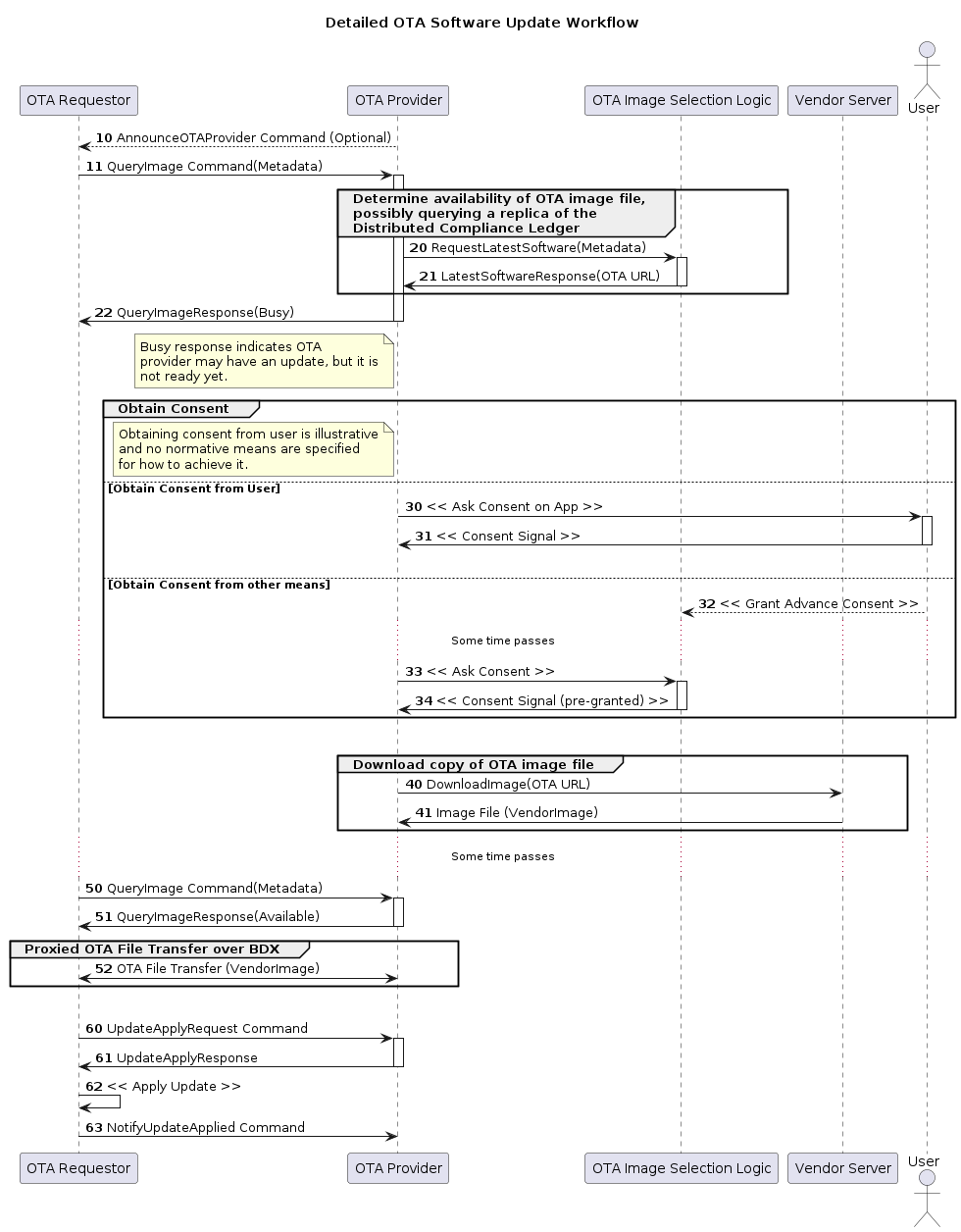
Figure 74. Detailed OTA Software Update Workflow
11.19.6 OTA Software Update Provider Cluster Definition
11.19.6.4. Data Types
StatusEnum:
0 UpdateAvailable
1 Busy
2 NotAvailable
3 DownloadProtocolNotSupported
ApplyUpdateActionEnum:
0 Proceed
1 AwaitNextAction
2 Discontinue
DownloadProtocolEnum:
0 BDXSynchronous
1 BDXAsynchronous
2 HTTPS
3 VendorSpecific
11.19.6.6. Commands
0x00 QueryImage Client ⇒ Server
0x01 QueryImageResponse Server ⇒ Client
0x02 ApplyUpdateRequest Client ⇒ Server
0x03 ApplyUpdateResponse Server ⇒ Client
0x04 NotifyUpdateApplied Client ⇒ Server
11.19.6.7. QueryImage Command:
0 VendorID vendor-id
1 ProductID uint16
2 SoftwareVersion uint32
3 ProtocolsSupported list[`DownloadProtocolEnum`]
4 HardwareVersion uint16
5 Location string
6 RequestorCanConsent bool
7 MetadataForProvider octstr
11.19.6.8. QueryImageResponse Command:
0 Status StatusEnum
1 DelayedActionTime uint32
2 ImageURI string
3 SoftwareVersion uint32
4 SoftwareVersionString string
5 UpdateToken octstr
6 UserConsentNeeded bool
7 MetadataForRequestor octstr
11.19.6.10. ApplyUpdateRequest Command:
0 UpdateToken octstr
1 NewVersion uint32
11.19.6.11. ApplyUpdateResponse Command:
0 Action ApplyUpdateActionEnum
1 DelayedActionTime uint32
11.19.6.12. NotifyUpdateApplied Command:
0 UpdateToken octstr
1 SoftwareVersion uint32
11.19.7. OTA Software Update Requestor Cluster Definition
11.19.7.4. Data Types
AnnouncementReasonEnum:
0 SimpleAnnouncement
1 UpdateAvailable
2 UrgentUpdateAvailable
UpdateStateEnum:
0 Unknown
1 Idle
2 Querying
3 DelayedOnQuery
4 Downloading
5 Applying
6 DelayedOnApply
7 RollingBack
8 DelayedOnUserConsent
ChangeReasonEnum:
0 Unknown
1 Success
2 Failure
3 TimeOut
4 DelayByProvider
ProviderLocationStruct:
1 ProviderNodeID node-id
2 Endpoint endpoint-no
11.19.7.5. Server Attributes
0 DefaultOTAProviders list[`ProviderLocationStruct`]
1 UpdatePossible bool
2 UpdateState `UpdateStateEnum`
3 UpdateStateProgress uint8
11.19.7.6. Commands
0x00 AnnounceOTAProvider Client ⇒ Server
11.19.7.7. AnnounceOTAProvider Command
0 ProviderNodeID node-id
1 VendorID vendor-id
2 AnnouncementReason `AnnouncementReasonEnum`
3 MetadataForNode octstr
4 Endpoint endpoint-no
11.19.7.8. Events
0 `StateTransition` INFO
1 `VersionApplied` CRITICAL
2 `DownloadError` INFO
StateTransition event:
0 PreviousState UpdateStateEnum
1 NewState UpdateStateEnum
2 Reason ChangeReasonEnum
3 TargetSoftwareVersion uint32
VersionApplied event:
0 SoftwareVersion uint32
1 ProductID uint16
DownloadError event:
0 SoftwareVersion uint32
1 BytesDownloaded uint64
2 ProgressPercent uint8
3 PlatformCode int64
11.20. Over-the-Air (OTA) Software Update File Format
The majority of devices will undergo an over-the-air (OTA) software update at some point during their operational lifecycle.
It cannot be assumed that the Node responsible for serving OTA updates (OTA Provider) has any specific knowledge about the internals of OTA Requestor Nodes that are receiving OTA updates.
This section provides a standardized header that SHALL be included in all OTA Software Images, in order to provide the necessary information for OTA Providers to validate images available for a given OTA Requestor.
Table 119. OTA Software Image File Layout:
FileIdentifier uint32
TotalSize uint64
HeaderSize uint32
Header `TLV Encoding Format`
Payload N/A
The Header is a TLV structure, encoded with anonymous outer tag, with the following format:
ota-image-header-struct => STRUCTURE [ tag-order ]
{
VendorID [0] : UNSIGNED INTEGER [ range 16bits ],
ProductID [1] : UNSIGNED INTEGER [ range 16bits ],
SoftwareVersion [2] : UNSIGNED INTEGER [ range 32bits ],
SoftwareVersionString [3] : STRING [ length 1..64 ],
PayloadSize [4] : UNSIGNED INTEGER [ range 64bits ],
MinApplicableSoftwareVersion [5, optional] : UNSIGNED INTEGER [ range 32bits ],
MaxApplicableSoftwareVersion [6, optional] : UNSIGNED INTEGER [ range 32bits ],
ReleaseNotesURL [7, optional] : STRING [ length 1..256 ],
ImageDigestType [8] : UNSIGNED INTEGER [ range 8bits ],
ImageDigest [9] : OCTET STRING [ length 0..64 ]
}
11.21. Bulk Data Exchange Protocol (BDX)
Nodes need the ability to transfer “files” between nodes. For example, uploading sensor data or diagnostics data to another node or downloading software update images from a software update server both require such a protocol.
This document defines a Bulk Data Exchange (BDX) protocol, where files are modeled as collections of bytes with some attached metadata.
11.21.3. Protocol Opcodes and Status Report Values
11.21.3.1. BDX Protocol Messages
• Vendor ID = 0x0000 (Matter Common)
• Protocol ID = PROTOCOL_ID_BDX
Table 120. BDX Protocol Opcodes:
Protocol Opcode Message
0x01 SendInit
0x02 SendAccept
0x03 Reserved for future use
0x04 ReceiveInit
0x05 ReceiveAccept
0x06... 0x0F Reserved for future use
0x10 BlockQuery
0x11 Block
0x12 BlockEOF
0x13 BlockAck
0x14 BlockAckEOF
0x15 BlockQueryWithSkip
11.21.3.2. BDX Status Codes
Table 121. BDX Status reports:
Status code Error
0x0012 LENGTH_TOO_LARGE
0x0013 LENGTH_TOO_SHORT
0x0014 LENGTH_MISMATCH
0x0015 LENGTH_REQUIRED
0x0016 BAD_MESSAGE_CONTENTS
0x0017 BAD_BLOCK_COUNTER
0x0018 UNEXPECTED_MESSAGE
0x0019 RESPONDER_BUSY
0x001F TRANSFER_FAILED_UNKNOWN_ERROR
0x0050 TRANSFER_METHOD_NOT_SUPPORTED
0x0051 FILE_DESIGNATOR_UNKNOWN
0x0052 START_OFFSET_NOT_SUPPORTED
0x0053 VERSION_NOT_SUPPORTED
0x005F UNKNOWN
11.21.5. Transfer Management Messages
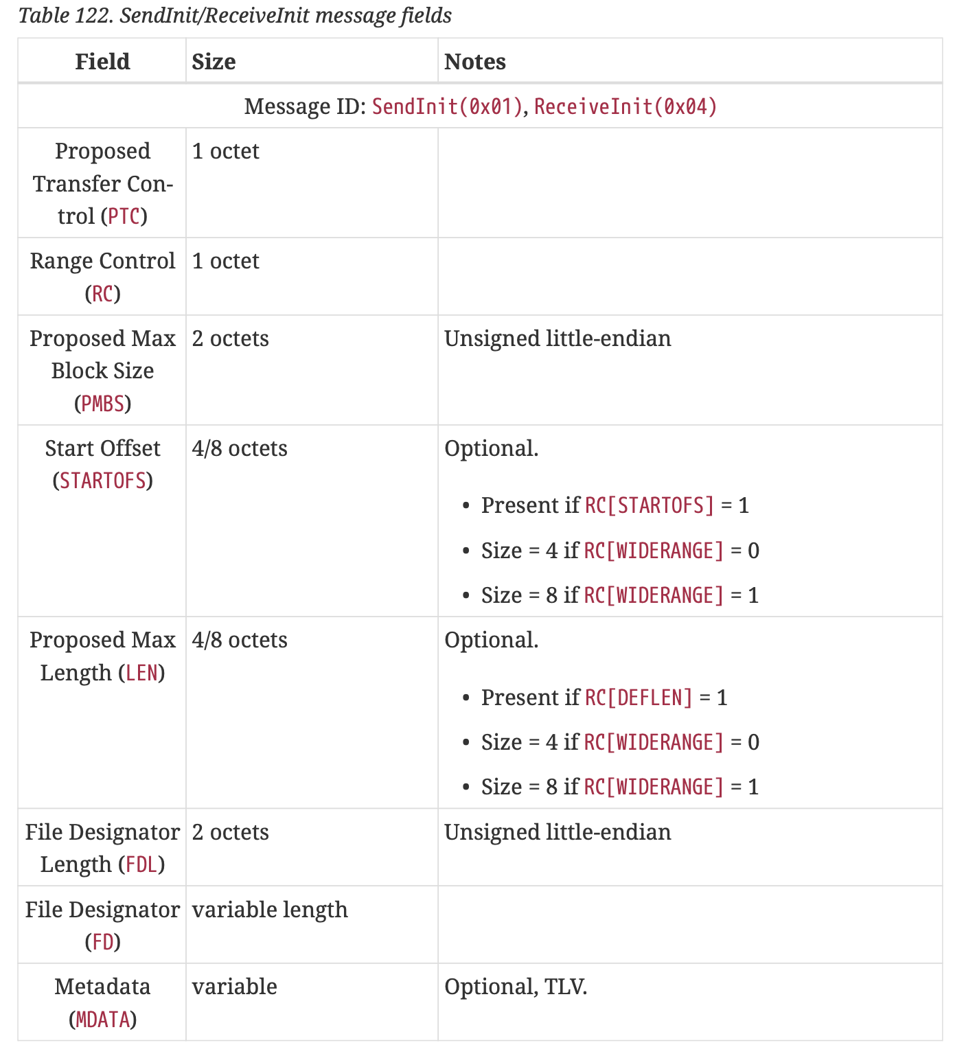
Table 122. SendInit/ReceiveInit message fields
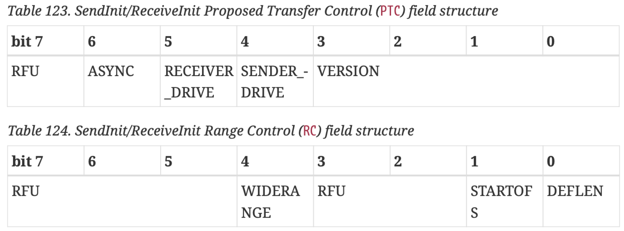
Table 123. SendInit/ReceiveInit Proposed Transfer Control (PTC) field structure, Table 124. SendInit/ReceiveInit Range Control (RC) field structure
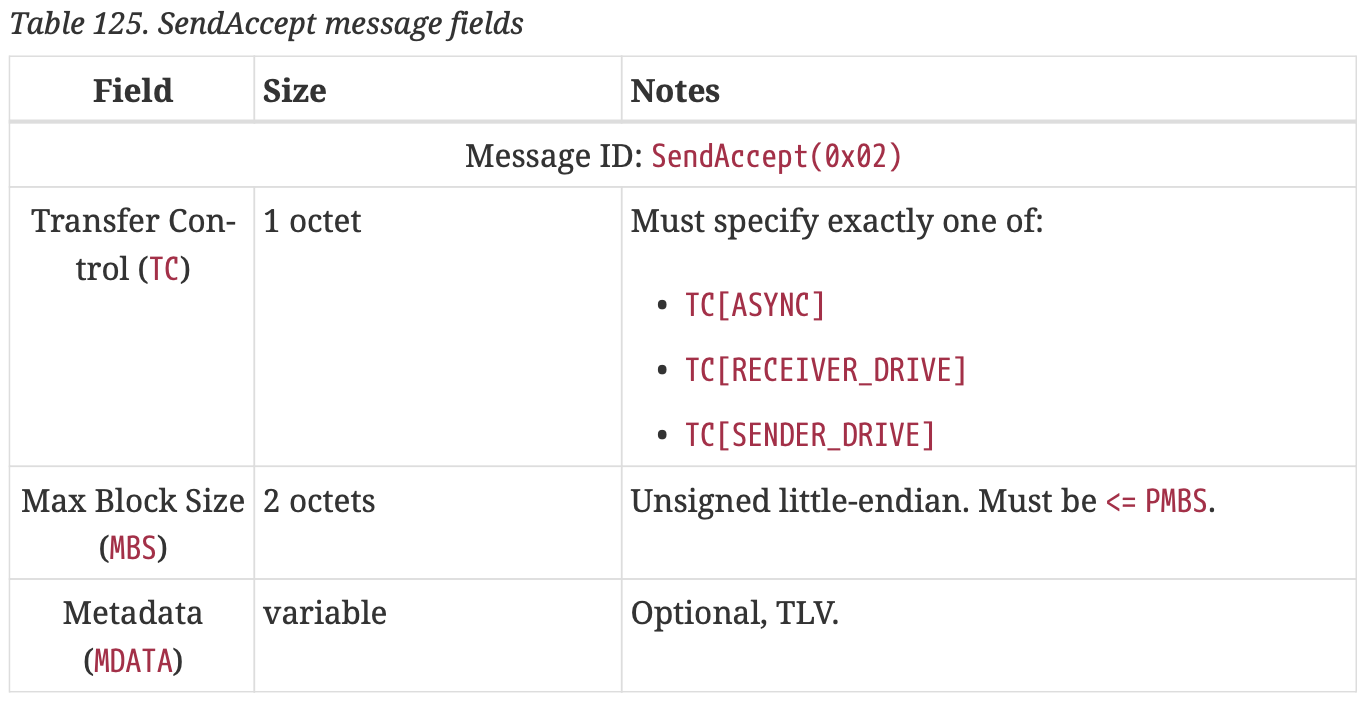
Table 125. SendAccept message fields
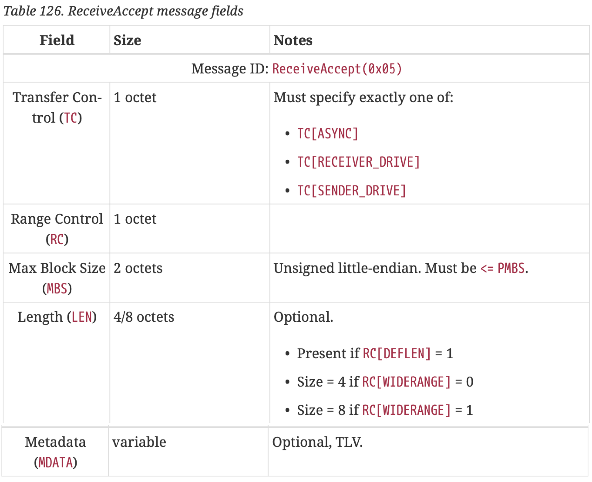
Table 126. ReceiveAccept message fields
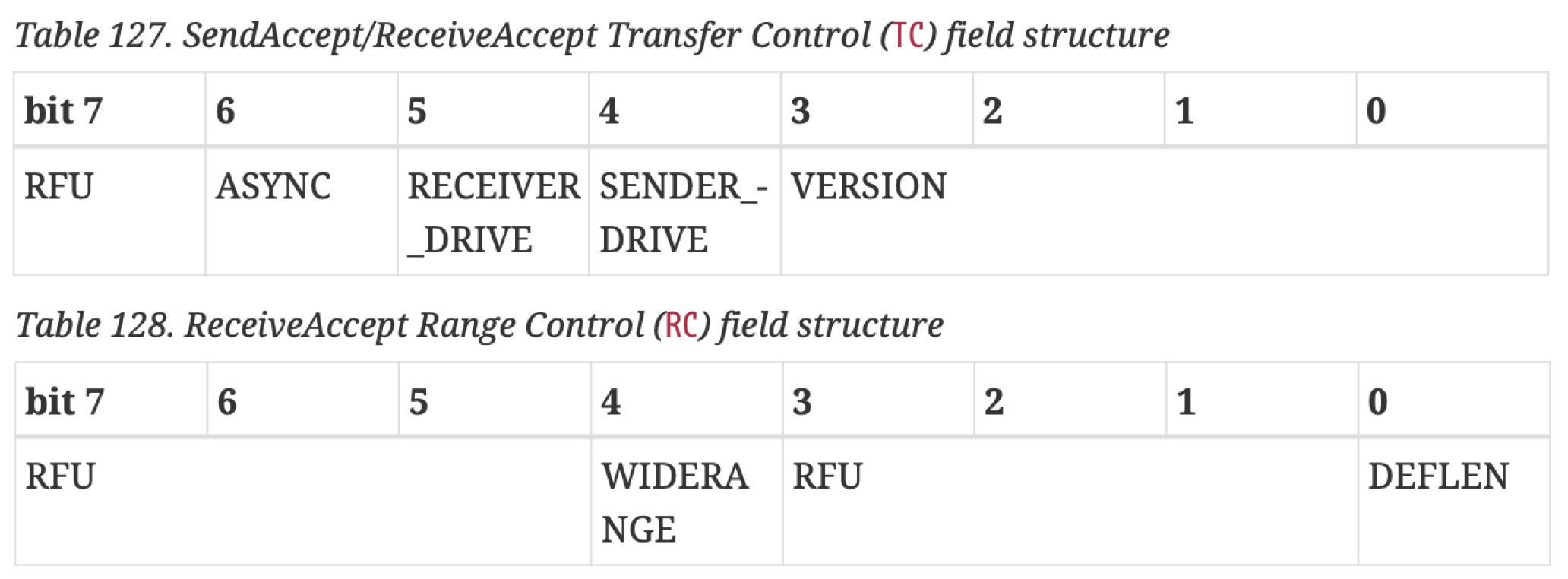
Table 127. SendAccept/ReceiveAccept Transfer Control (TC) field structure, Table 128. ReceiveAccept Range Control (RC) field structure
11.21.6. Data Transfer Messages
11.21.6.1. Block Ordering Rules
11.21.6.2. BlockQuery Message
11.21.6.3. BlockQueryWithSkip Message
11.21.6.4. Block Message
11.21.6.5. BlockEOF Message
11.21.6.6. BlockAck
11.21.6.7. BlockAckEOF
11.21.7. Synchronous Transfers Message Flows
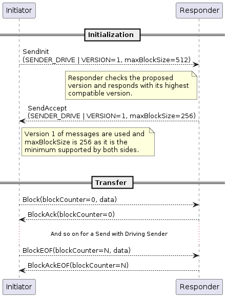
Figure 75. Version negotiation: both participants support V1 of the protocol
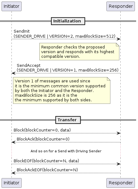
Figure 76. Version negotiation: Initiator supports V2 of the protocol, while Responder supports V1
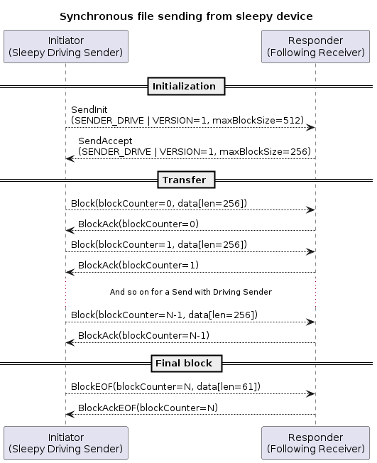
Figure 77. Synchronous file sending from sleepy device acting as driving Sender
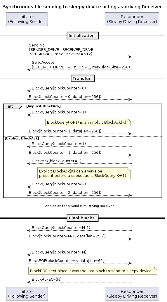
Figure 78. Synchronous file sending to sleepy device acting as driving Receiver
…
11.22. Distributed Compliance Ledger
11.22.1. Scope & Purpose
The CSA’s
DCL (Distributed Compliance Ledger)is a distributed store of information used for tracking certification status and Vendor maintained information such as, but not limited to,product name,product description, andfirmware URL.This information is cryptographically secured by digital signatures and is made available via CSA approved synchronized servers or nodes that are geographically distributed.
Distributed Compliance Ledger is an open-source project designed to:
• Act as a data store for device models' information and their compliance status. • Act as a secure distribution point of device meta data as made available by vendors. • Act as a secure distribution point of Product Attestation Authorities certificates.
The DCL is owned and hosted by CSA members in a way that:
• Write access to Ledger is restricted
• Read access from DCL is public
11.22.2. Schemas
Ledger data is available in following schemas:
• Vendor Schema
• PAA Schema
• DeviceModel Schema
• DeviceSoftwareVersionModel Schema
• Compliance / Compliance test result Schema
11.22.3. Vendor Schema
Name Type
----- ------
VendorID vendor-id
VendorName string
CompanyLegalName string
CompanyPreferredName string
VendorLandingPageUrl string
11.22.4. PAA Schema
PAACert string
PAASubject string
PAASubjectKeyID string
11.22.5. DeviceModel Schema
VendorID vendor-id
ProductID uint16
DeviceTypeID devtype-id
ProductName string
ProductLabel string
PartNumber string
CommissioningCustomFlow uint8
CommissioningCustomFlowUrl string
CommissioningModeInitialStepsHint map32
CommissioningModeInitialStepsInstruction string
CommissioningModeSecondaryStepsHint map32
CommissioningModeSecondaryStepsInstruction string
UserManualUrl string
SupportUrl string
ProductURL string
LsfUrl string
LsfRevision uint16
11.22.6. DeviceSoftwareVersionModel Schema
VendorID vendor-id
ProductID uint16
SoftwareVersion uint32
SoftwareVersionString string
CDVersionNumber uint16
FirmwareInformation string
SoftwareVersionValid boolean
OtaUrl string
OtaFileSize uint64
OtaChecksum string
OtaChecksumType uint16
MinApplicableSoftwareVersion uint32
MaxApplicableSoftwareVersion uint32
ReleaseNotesUrl string
11.22.7. DeviceSoftwareCompliance / Compliance test result Schema
VendorID vendor-id
ProductID uint16
SoftwareVersion uint32
SoftwareVersionString string
CDVersionNumber uint16
SoftwareVersionCertificationStatus `SoftwareVersionCertificationStatusEnum`
CDCertificateID string
11.22.7.2. SoftwareVersionCertificationStatusEnum:
0 dev-test
1 provisional
2 certified
3 revoked
Chapter 12. Multiple Fabrics
12.1. Multiple Fabrics
The Multiple Fabric feature allows a Node to be commissioned to multiple separately-administered Fabrics.
With this feature a current Administrator can (with user consent) allow the Commissioner for another fabric to commission that Node within its Fabric.
The new Commissioner MUST have their own Node Operational Certificate (NOC) issued by its Trusted Root Certificate Authority (TRCA).
Once commissioning is completed and the Node is properly configured, Administrators on the newly joined Fabric have access to the Node and can perform all administrative tasks.
Chapter 13. Security Requirements
Each Matter security and privacy requirement references the underlying
countermeasure (CM)andthreat (T)in the Threat Model that motivated the need for the requirement.
13.2. Device vs. Node
For some requirements, we need to differentiate between a Node (the entity which supports the Matter protocol stack) and a Device (a piece of equipment containing one or more Nodes).
13.4. Factory Reset
13.7. Threats and Countermeasures
Threats: Tx
Countermeasures: CMx
This section lists identified threats to Matter and countermeasures to mitigate those threats. This section is meant to be informational and not as normative requirements.
Appendix A: Tag-length-value (TLV) Encoding Format
A.1. Scope & Purpose
The Matter TLV (Tag-Length-Value) format is a generalized encoding method for simple structured data, used throughout this specification.
Values in the Matter TLV format are encoded as TLV elements. Each TLV element has a type.
Element types fall into two categories:
primitive types container types
A.2. Tags
A TLV element includes an optional numeric tag that identifies its purpose. A TLV element without a tag is called an
anonymous element.For elements with tags, two categories of tags are defined:
profile-specific context-specific
A.2.1. Profile-Specific Tags:
Profile-specific tags identify elements globally.
A profile-specific tag is a 64-bit number composed of the following fields:
• 16-bit Vendor ID
• 16-bit profile number
• 32-bit tag number
A.2.2. Context-Specific Tags:
Context-specific tags identify elements within the context of a containing structure element.
A context-specific tag consists of a single 8-bit tag number.
A.2.3. Anonymous Tags:
A special "anonymous tag" is used to denote TLV elements that lack a tag value.
A.2.4. Canonical Ordering of Tags:
ordering rules SHALL be used:
• `Anonymous` tags SHALL be ordered before all other tags.
• `Context-specific` tags SHALL be ordered before `profile-specific` tags.
A.3. Lengths
Depending on its type, a TLV element may contain a length field that gives the length, in octets, of the element’s value field.
A.4. Primitive Types
The Matter TLV format supports the following primitive types:
• Signed integers
• Unsigned integers
• UTF-8 Strings
• Octet Strings
• Single or double-precision floating point numbers
• Booleans
• Nulls
Of the primitive types, integers, floating point numbers, booleans and nulls have a predetermined length specified by their type.
Octet strings and UTF-8 strings include a length field that gives their lengths in octets.
A.5. Container Types
The Matter TLV format supports the following container types:
• Structures
• Arrays
• Lists
A.6. Element Encoding
A TLV element is encoded a single
control octet, followed by a sequence oftag,lengthandvalueoctets.
Control |
Octet Tag |
Length |
Value |
|---|---|---|---|
1 octet |
0 to 8 octets |
0 to 8 octets |
Variable |
A.7. Control Octet Encoding
A.7.1. Element Type Field
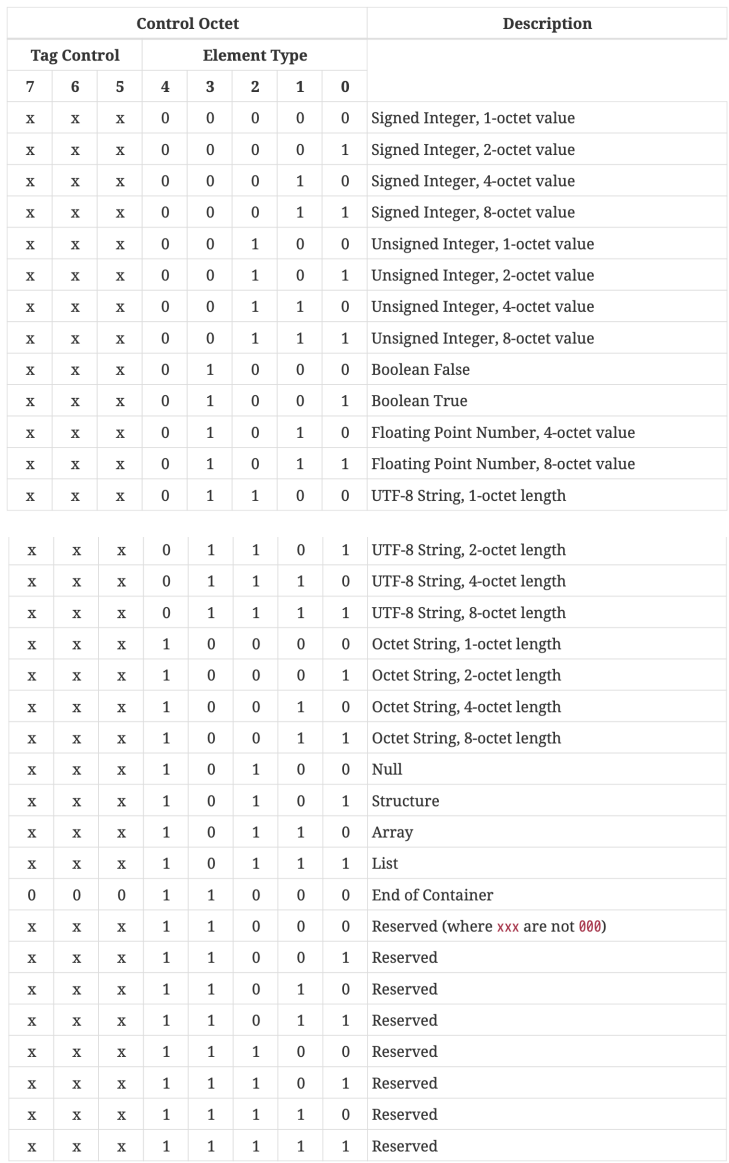
The element type field encodes the element’s type as well as how the corresponding length and value fields are encoded.
Control Octet Description
Tag Control Element Type
x x x 0 0 0 0 0 Signed Integer, 1-octet value
x x x 0 0 0 0 1 Signed Integer, 2-octet value
x x x 0 0 0 1 0 Signed Integer, 4-octet value
x x x 0 0 0 1 1 Signed Integer, 8-octet value
x x x 0 0 1 0 0 Unsigned Integer, 1-octet value
x x x 0 0 1 0 1 Unsigned Integer, 2-octet value
x x x 0 0 1 1 0 Unsigned Integer, 4-octet value
x x x 0 0 1 1 1 Unsigned Integer, 8-octet value
x x x 0 1 0 0 0 BooleanFalse
x x x 0 1 0 0 1 BooleanTrue
x x x 0 1 0 1 0 Floating Point Number, 4-octet value
x x x 0 1 0 1 1 Floating Point Number, 8-octet value
x x x 0 1 1 0 0 UTF-8 String, 1-octet length
x x x 0 1 1 0 1 UTF-8 String, 2-octet length
x x x 0 1 1 1 0 UTF-8 String, 4-octet length
x x x 0 1 1 1 1 UTF-8 String, 8-octet length
x x x 1 0 0 0 0 Octet String, 1-octet length
x x x 1 0 0 0 1 Octet String, 2-octet length
x x x 1 0 0 1 0 Octet String, 4-octet length
x x x 1 0 0 1 1 Octet String, 8-octet length
x x x 1 0 1 0 0 Null
x x x 1 0 1 0 1 Structure
x x x 1 0 1 1 0 Array
x x x 1 0 1 1 1 List
0 0 0 1 1 0 0 0 EndofContainer
x x x 1 1 0 0 0 Reserved (where xxx are not 000)
x x x 1 1 0 0 1 Reserved
x x x 1 1 0 1 0 Reserved
x x x 1 1 0 1 1 Reserved
x x x 1 1 1 0 0 Reserved
x x x 1 1 1 0 1 Reserved
x x x 1 1 1 1 0 Reserved
x x x 1 1 1 1 1 Reserved
A.7.2. Tag Control Field
Control Octet Description
Tag Control Element Type
0 0 0 x x x x x Anonymous Tag Form, 0 octets
0 0 1 x x x x x Context-specific Tag Form, 1 octet
0 1 0 x x x x x Common Profile Tag Form, 2 octets
0 1 1 x x x x x Common Profile Tag Form, 4 octets
1 0 0 x x x x x Implicit Profile Tag Form, 2 octets
1 0 1 x x x x x Implicit Profile Tag Form, 4 octets
1 1 0 x x x x x Fully-qualified Tag Form, 6 octets
1 1 1 x x x x x Fully-qualified Tag Form, 8 octets
A.8. Tag Encoding
Tags are encoded in 0, 1, 2, 4, 6 or 8 octet widths as specified by the tag control field.
Tags consist of up to three numeric fields: a
Vendor IDfield, aprofile numberfield, and atag numberfield.
The tag fields are ordered as follows:
Vendor ID Profile Number Tag Number
0 or 2 octets 0 or 2 octets 1, 2, or 4 octets
A.8.1. Fully-Qualified Tag Form
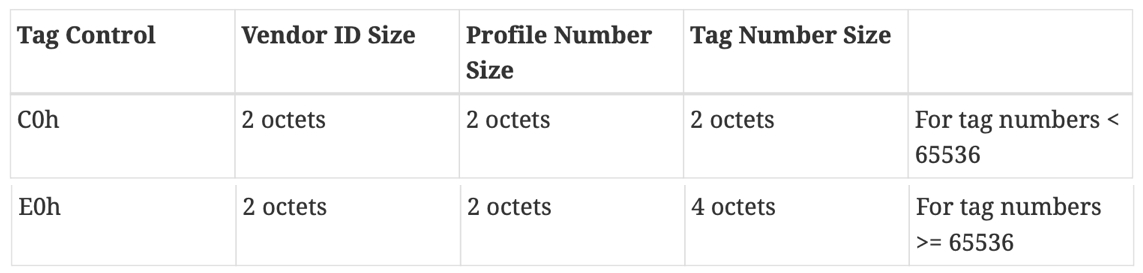
Two variants of this form are supported, one with a 16-bit tag number and one with a 32-bit tag number.
E0: 111 00000
C0: 110 00000
A.8.2. Implicit Profile Tag Form
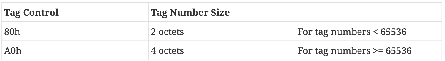
80: 100 00000
A0: 101 00000
A.8.3. Common Profile Tag Form
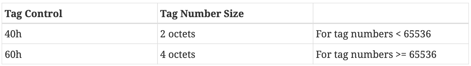
60: 011 00000
40: 010 00000
A.8.4. Context-Specific Tag Form

20: 001 00000
A.8.5. Anonymous Tag Form

00: 000 00000
A.9. Length Encoding
Length fields are encoded in 0, 1, 2, 4 or 8 octet widths, as specified by the element type field.
The choice of width for the length field is up to the discretion of the sender, implying that a sender can choose to send more length octets than strictly necessary to encode the value.
A.10. End of Container Encoding
The end of a container type is marked with a special element called the end-of-container element.
18: 000 11000
A.11. Value Encodings
A.11.1. Integers

An integer element is encoded as follows
A.11.2. UTF-8 and Octet Strings
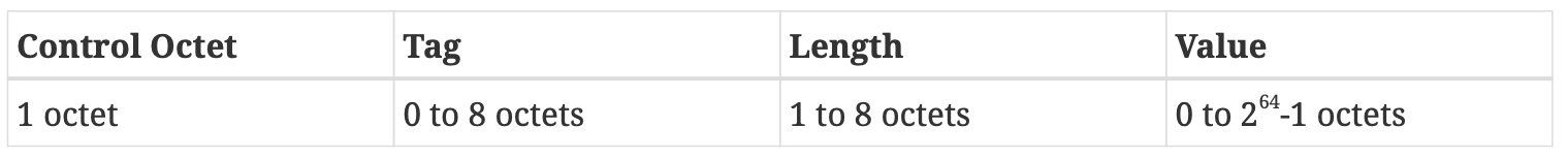
UTF-8 and octet strings are encoded as follows
A.11.3. Booleans
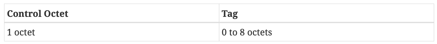
Boolean elements are encoded as follows
A.11.4. Arrays, Structures and Lists

Array, structure and list elements are encoded as follows
A.11.5. Floating Point Numbers

A floating point number is encoded as follows
A.11.6. Nulls

A Null value is encoded as follows
A.12. TLV Encoding Examples
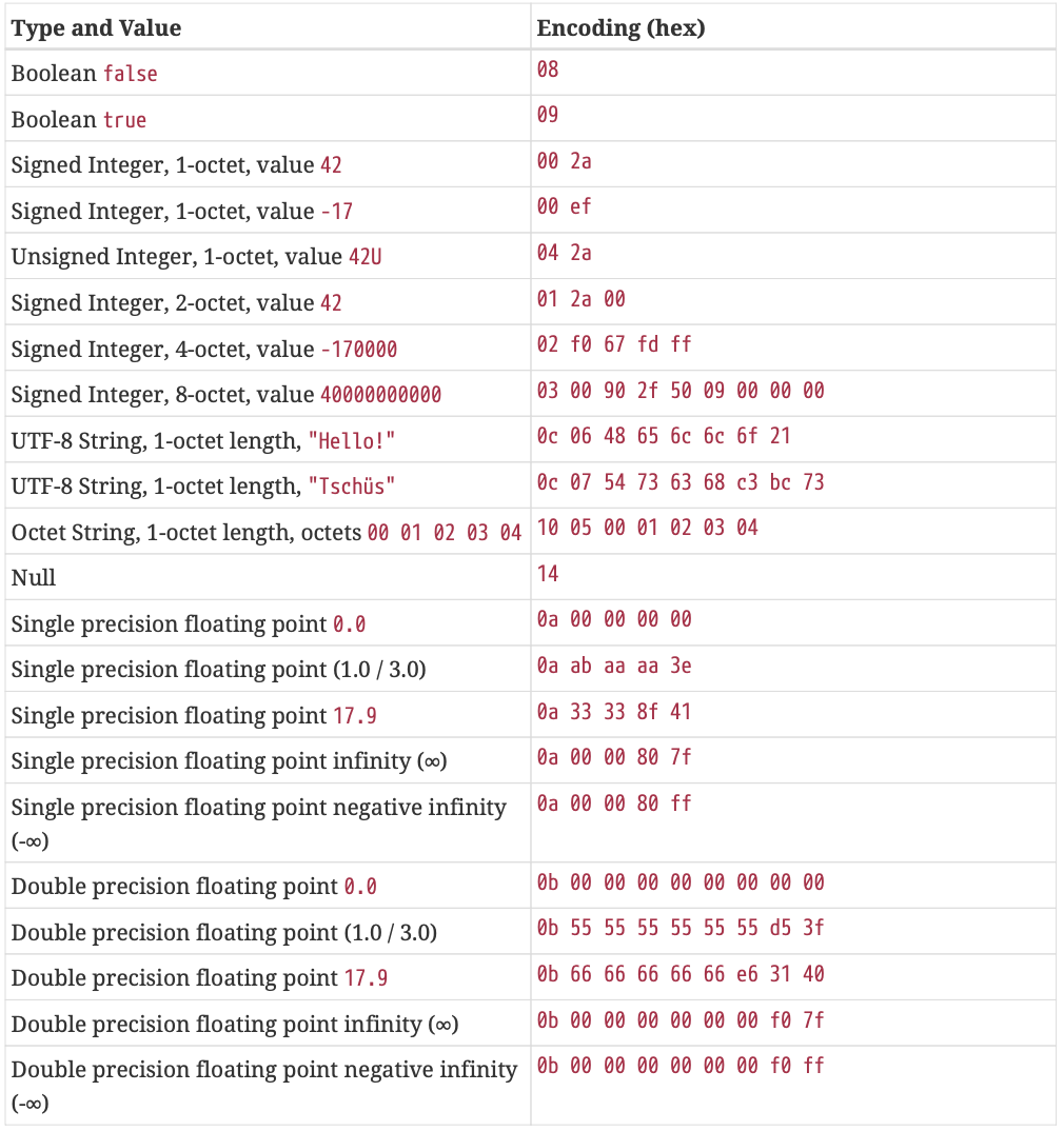
Table 137. Sample encoding of primitive types
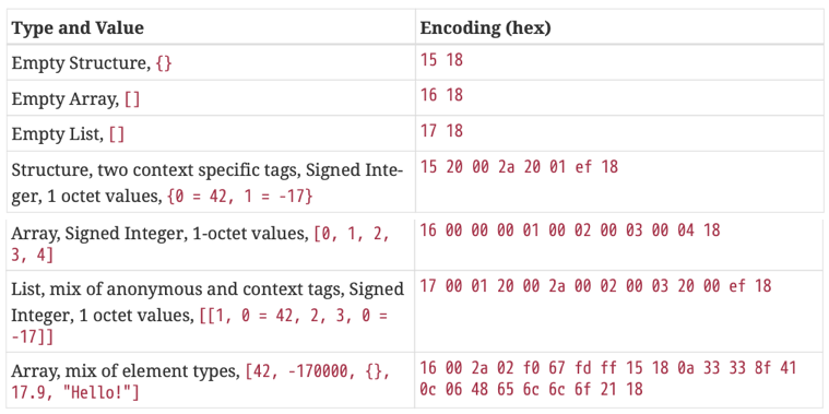
Table 138. Sample encoding of containers
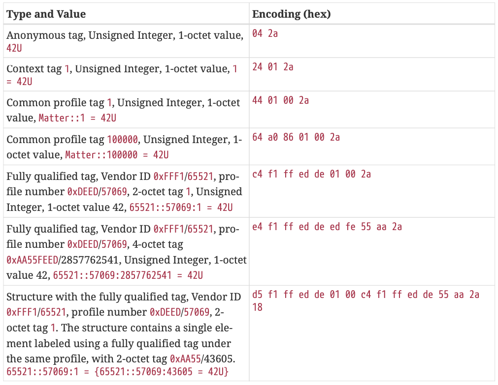
Table 139. Sample encoding of different tag types
Appendix B: Tag-length-value (TLV) Schema Definitions
B.1. Introduction
A TLV Schema provides a simple textual description of the structure of data encoded in the Matter TLV format.
B.1.1. Basic Structure:
/* Sensor sample structure */
sensor-sample => STRUCTURE
{
timestamp [1] : UNSIGNED INTEGER [ range 32-bits ],
value [2] : FLOAT64,
}
B.1.4. Namespaces:
namespace a {
x => STRING,
other-x => b.x
}
namespace b {
x => SIGNED INTEGER
}
B.1.6. Tagging:
certificate [my-protocol:1] => STRUCTURE
{
serial-num [1] : OCTET STRING,
...
}
B.2. Definitions
B.2.1. Type Definition (type-def)
Type Definition Syntax:
type-name [ qualifier ] => type-or-ref
type-or-ref:
`type`
`type-ref`
`type`:
ANY
ARRAY
ARRAY OF
BOOLEAN
CHOICE OF
FLOAT32
FLOAT64
LIST
LIST OF
NULL
OCTET STRING
SIGNED INTEGER
STRING
STRUCTURE
UNSIGNED INTEGER
`type-ref`:
type-name
scoped-type-name
qualifier:
tag
B.2.2. FIELD GROUP Definition (field-group-def)
FIELD GROUP Definition Syntax:
field-group-name => FIELD GROUP { `field-group-members` }
`field-group-members`:
`field-group-member`
field-group-members, field-group-member
`field-group-member`:
identifier [ `id-qualifier` ] : type-or-ref // field definition
includes field-group-name // field group include
`id-qualifier`:
tag // SHALL be present
optional
FIELD GROUP Definition Examples:
`common-sensor-sample-fields` => FIELD GROUP
{
timestamp [1] : UNSIGNED INTEGER [ range 32-bits ],
}
temperature-sensor-sample => STRUCTURE [tag-order]
{
includes `common-sensor-sample-fields`,
value [2] : FLOAT64,
}
humidity-sensor-sample => STRUCTURE [tag-order]
{
includes `common-sensor-sample-fields`,
value [2] : UNSIGNED INTEGER [ range 64-bits ],
}
B.2.3. Namespace Definition (namespace-def)
Namespace Definition Syntax:
namespace `ns-name` { `ns-scoped-defs` }
`ns-name`:
name
scoped-name
`ns-scoped-defs`:
`ns-scoped-def`
ns-scoped-defs, ns-scoped-def
`ns-scoped-def`:
`type-def`
`field-group-def`
`protocol-def`
`namespace-def`
Namespace Definition Examples:
namespace abc
{
property => FLOAT32 [ range 0..50 ],
point => STRUCTURE
{
day [0] : UNSIGNED INTEGER,
prop [1] : property
}
}
namespace matter.protocols.aaa
{
config => STRUCTURE
{
points [0] : ARRAY OF abc.point,
...
}
}
B.2.4. PROTOCOL Definition (protocol-def)
PROTOCOL Definition Syntax:
name => PROTOCOL [ qualifier ] { protocol-scoped-defs }
qualifier:
id
protocol-scoped-defs:
protocol-scoped-def
protocol-scoped-defs, protocol-scoped-def
protocol-scoped-def:
type-def
field-group-def
namespace-def
PROTOCOL Definition Example:
namespace some.names {
my-protocol => PROTOCOL [ VENDOR:0x0008 ]
{
laser-transducer-metadata [1] => STRUCTURE
{
serial-num [1] : OCTET STRING,
...
},
optics-array [2] => ARRAY OF optical-specification
}
}
B.2.5. VENDOR Definition (vendor-def)
VENDOR Definition Syntax:
name => VENDOR [ `qualifier` ]
`qualifier`:
id
B.3. Types
B.3.1. ARRAY / ARRAY OF
ARRAY Syntax:
ARRAY [ qualifier ] OF type-or-ref // uniform array
ARRAY [ qualifier ] { type-pattern } // pattern array
qualifier (optional):
length
nullable
type-pattern:
type-pattern-item
type-pattern, type-pattern-item
type-pattern-item:
type-or-ref quantifier // unnamed item
identifier : type-or-ref quantifier // named item
quantifier (optional):
*
+
{ count }
{ min..max }
{ min.. }
ARRAY Example:
supported-country-codes => ARRAY [ length 0..10 ] OF STRING [ length 2 ]
weather-tuple => ARRAY
{
timestamp : UNSIGNED INTEGER [ range 32-bits ],
temperature : FLOAT64,
relative-humidity : UNSIGNED INTEGER [ range 0..100 ],
precipitation : UNSIGNED INTEGER [ range 0..100 ],
}
named-vector => ARRAY
{
name : STRING,
FLOAT64 *,
}
B.3.2. BOOLEAN
BOOLEAN Syntax:
BOOLEAN [ qualifier ]
qualifier (optional):
nullable
BOOLEAN Example:
pathlight-enabled => BOOLEAN
B.3.3. FLOAT32 / FLOAT64
FLOAT Syntax:
FLOAT32 [ qualifier ]
FLOAT64 [ qualifier ]
qualifier (optional):
range
nullable
FLOAT Example:
set-value => FLOAT32 [ range 0..50 ]
B.3.4. SIGNED INTEGER / UNSIGNED INTEGER
Integer Syntax:
SIGNED INTEGER [ qualifier ] { enum }
UNSIGNED INTEGER [ qualifier ] { enum }
qualifier (optional):
range
nullable
enum:
identifier = int-value
Integer Examples:
sensor-value => SIGNED INTEGER [ range -100..100 ]
counter => UNSIGNED INTEGER [ range 32-bits ]
B.3.5. LIST / LIST OF
LIST Syntax:
LIST [ list-qualifier ] OF type-or-ref
LIST [ list-qualifier ] { type-pattern }
list-qualifier (optional):
length
nullable
type-pattern:
type-or-ref quantifier // unnamed item
identifier [ qualifier ] : type-or-ref quantifier // named item
quantifier (optional):
*
+
{ count }
{ min..max }
{ min.. }
qualifier (optional):
tag
B.3.6. OCTET STRING
OCTET STRING Syntax:
OCTET STRING [ qualifier ]
qualifier (optional):
length
nullable
OCTET STRING Example:
address => OCTET STRING [ length 8 ]
B.3.7. NULL
NULL
NULL Example:
serial-num => CHOICE OF { STRING, UNSIGNED INTEGER, NULL }
B.3.8. STRING
STRING Syntax:
STRING [ qualifier ]
qualifier (optional):
length
nullable
STRING Example:
name-field => STRING [ length 0..32 ]
B.3.9. STRUCTURE
STRUCTURE Syntax:
STRUCTURE [ structure-qualifier ] { structure-fields }
structure-qualifier (optional):
extensible
order
nullable
structure-fields:
structure-field
structure-fields, structure-field
structure-field:
identifier [ id-qualifier ] : type-or-ref
includes field-group-name
id-qualifier:
tag
optional
STRUCTURE with CHOICE OF Field Example:
user-information => STRUCTURE [ extensible ]
{
user-id [1] : CHOICE OF
{
UNSIGNED INTEGER,
STRING
}
}
STRUCTURE with CHOICE OF Field with Default Tag Example:
user-information => STRUCTURE [ extensible ]
{
user-id : CHOICE OF
{
id [1] : UNSIGNED INTEGER,
name [2] : STRING
}
}
B.4. Pseudo-Types
B.4.1. ANY
ANY Syntax:
ANY
ANY Example:
app-defined-metadata => ANY
B.4.2. CHOICE OF
CHOICE OF Syntax:
CHOICE [ qualifier ] OF { alternates }
qualifier (optional):
nullable
alternates:
alternate
alternates, alternate
alternate:
type-or-ref
identifier [ id-qualifier ] : type-or-ref
id-qualifier:
tag
CHOICE OF Invalid Alternates Merge Example:
CHOICE OF {
CHOICE OF {
foo: STRING,
bar: UNSIGNED INTEGER
},
CHOICE OF {
foo: BOOLEAN,
bar: FLOAT64
}
}
CHOICE OF Valid Alternates Merge Example:
CHOICE OF {
alt1: CHOICE OF {
foo: STRING,
bar: UNSIGNED INTEGER
},
alt2: CHOICE OF {
foo: BOOLEAN,
bar: FLOAT64
}
}
B.5. Qualifiers
Qualifiers are annotations that provide additional information regarding the use or interpretation of a schema construct.
B.5.1. any-order / schema-order / tag-order
The any-order, schema-order and tag-order qualifiers MAY be used to specify a particular order for the encoding of fields within a STRUCTURE.
Order Qualifiers Syntax:
STRUCTURE [ any-order ]
STRUCTURE [ schema-order ]
STRUCTURE [ tag-order ]
B.5.2. extensible
The extensible qualifier is only allowed on STRUCTURE types, and declares that the structure MAY be extended by the inclusion of fields not listed in its definition.
When a structure is extended in this way, any new fields that are included SHALL use tags that are distinct from any of those associated with defined or included fields.
extensible Qualifier Syntax:
STRUCTURE [ extensible ]
extensible Qualifier Example:
user-information => STRUCTURE [ extensible ]
{
user-id [1] : UNSIGNED INTEGER,
first-name [2] : STRING,
last-name [3] : STRING,
email-address [4] : STRING,
}
B.5.3. id
id Qualifier Syntax:
vendor-name => VENDOR [ id uint-value ]
protocol-name => PROTOCOL [ id uint-value ]
protocol-name => PROTOCOL [ id uint-value:uint-value ]
protocol-name => PROTOCOL [ id vendor-name:uint-value ]
id Qualifier Examples:
MATTER-VENDOR-AB => VENDOR [ 0x00AB ]
// Equivalent definitions of the protocol introduced by MATTER-VENDOR-AB
vendor-ab-prot8 => PROTOCOL [ 0x00AB0008 ]
vendor-ab-prot8 => PROTOCOL [ 0x00AB:0x0008 ]
vendor-ab-prot8 => PROTOCOL [ MATTER-VENDOR-AB:8 ]
B.5.4. length
length Qualifier Syntax:
type [ length count ] // exactly count
type [ length min..max ] // between min and max (inclusive)
type [ length min.. ] // at least min
B.5.5. nullable
nullable Qualifier Syntax:
type [ nullable ]
B.5.6. optional
optional Qualifier Syntax:
...
field-name [ optional ] : type-or-ref,
...
B.5.7. range
range Qualifier Syntax:
integer-type [ range min..max ]
integer-type [ range 8-bits ]
integer-type [ range 16-bits ]
integer-type [ range 32-bits ]
integer-type [ range 64-bits ]
B.5.8. tag
The tag qualifier is allowed on type names, field names within a STRUCTURE (STRUCTURE Fields) or FIELD GROUP, item names within a LIST (LIST Item Tags), alternate names within a CHOICE OF (CHOICE OF Fields).
tag Qualifier Syntax:
identifier [ tag-num ]
identifier [ protocol-id:tag-num ]
identifier [ protocol-name:tag-num ]
identifier [ *:tag-num ]
identifier [ anonymous ]
B.5.9. Documentation and Comments
Documentation and Comments Example:
/* Sensor sample structure */
sensor-sample => STRUCTURE
{
timestamp [1] : UNSIGNED INTEGER,
value [2] : FLOAT64,
}
Appendix C: Tag-length-value (TLV) Payload Text Representation Format
C.1. Introduction
This section describes a means by which to depict TLV payloads in a more user-friendly, textual representation.
C.3. Examples
C.3.1. TLV Schema:
temp-sample => STRUCTURE
{
timestamp [1] : UNSIGNED INTEGER [ range 32-bits ],
temperature [2] : FLOAT64,
}
accel-sample => STRUCTURE
{
x [1] : SIGNED INTEGER [ range 16-bits ],
y [2] : SIGNED INTEGER [ range 16-bits ],
z [3] : SIGNED INTEGER [ range 16-bits ]
}
temp-features-enum => UNSIGNED INTEGER [ range 0...3 ]
{
HAS_TEMP_COMPENSATION = 1,
SUPPORTS_THRESHOLD_TRIGGERS = 2
}
accel-features-enum => UNSIGNED INTEGER [ range 0...3 ]
{
SUPPORTS_HIGH_SAMPLING = 1,
SUPPORTS_THRESHOLD_TRIGGERS = 2
}
sensor-state => STRUCTURE
{
temperature-samples [1] : ARRAY OF temperature-sample,
accel-samples [2] : ARRAY OF accel-sample,
manufacturer-name [3]: STRING,
// List of lists. If present, one or more of the feature lists will be present.
feature-map [4,optional] : LIST {
temp-features[1]: ARRAY OF temp-features-enum,
accel-features[2]: ARRAY OF accel-features-enum
},
supports-idle [5] : BOOLEAN,
num-power-modes[6]: UNSIGNED INTEGER [ range 8-bits ],
supported-extensions[7] : LIST OF STRING
}
C.3.2. TLV Payloads:
temperature-sample-example =
{
timestamp (1) = 2023423U,
temperature (2) = 72.0
}
accelerometer-sample-example =
{
x (1) = 10,
y (2) = 20,
z (3) = 30
}
sensor-state-example =
{
temperature-samples (1) =
[
{
timestamp (1) = 2023423U,
temperature (2) = 72.0
}, {
temperature (2) = 69.2
},
],
accel-samples (2) =
[
{
x (1) = 10,
y (2) = 20,
z (3) = 30,
},
{
x (1) = 1,
y (2) = 2,
z (3) = 3,
},
],
manufacturer-name (3) = "SmartSensors Ltd",
feature-map (4) =
[[
temp-features (1) =
[
HAS_TEMP_COMPENSATION (1),
SUPPORTS_THRESHOLD_TRIGGERS (2)
],
accel-features (2) =
[
SUPPORTS_THRESHOLD_TRIGGERS (2)
]
]],
supports-idle (5) = false,
num-power-modes (6) = 2U,
supported-extensions (7) =
[[
SMARTSENSORS::SensingProtocol:Extension (0x00ef::0x00aa:0x01) = "SUPPORTS_SMART_AVERAGING"
]]
}
Appendix D: Status Report Messages
The StatusReport is a core message that encapsulates the result of an operation which a responder sends as a reply for requests sent from an initiator, using a common message of the Secure Channel Protocol (Protocol ID = PROTOCOL_ID_SECURE_CHANNEL).
D.3. Message Format
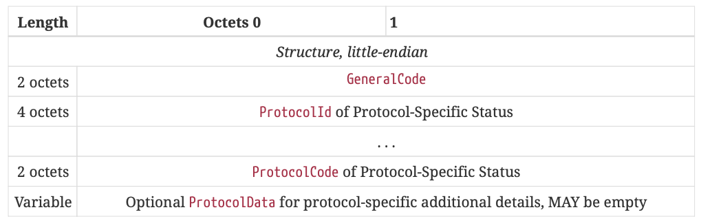
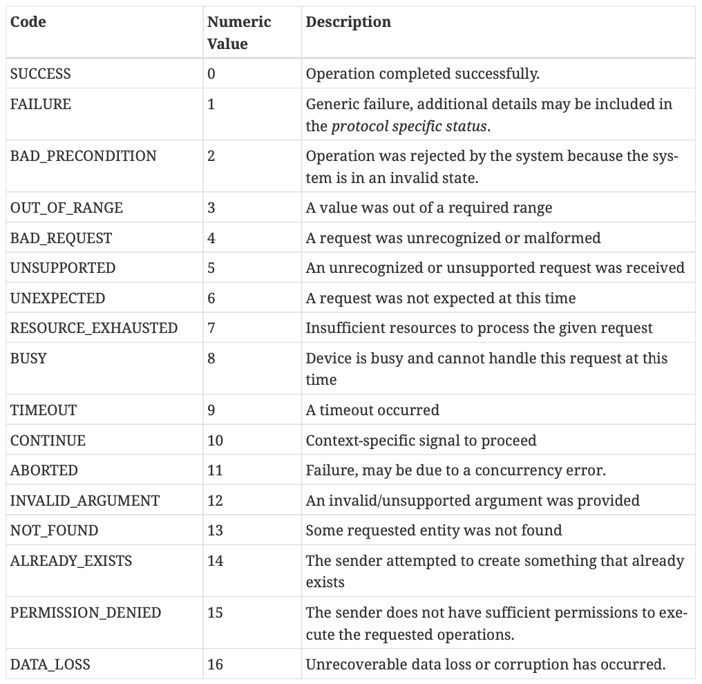
general status codes are defined
Example: No ProtocolData present:
StatusReport(
GeneralCode: FAILURE,
ProtocolId: BDX,
ProtocolCode: START_OFFSET_NOT_SUPPORTED
)
=> Encodes as:
01 00 02 00 00 00 52 00
StatusReport(
GeneralCode: SUCCESS,
ProtocolId: {VendorID=0xFFF1, ProtocolId=0xAABB},
ProtocolCode: 0
)
=> Encodes as:
00 00 BB AA F1 FF 00 00
Example: Additional ProtocolData present:
StatusReport(
GeneralCode: FAILURE,
ProtocolId: {VendorID=0xFFF1, ProtocolId=0xAABB},
ProtocolCode: 9921,
ProtocolData: [0x55, 0x66, 0xEE, 0xFF]
)
=> Encodes as: 01 00 BB AA F1 FF C1 26 55 66 EE FF
Appendix E: Matter-Specific ASN.1 Object Identifiers (OIDs)
Matter defines custom ASN.1 OID values, which are listed in the table below under the 1.3.6.1.4.1.37244 private arc. These OID values are assigned by the Connectivity Standards Alliance for use with Matter.

Table 140. ASN.1 Matter-Specific Object Identifiers
Appendix F: Cryptographic test vectors for some procedures
This subsection contains worked examples of encoding a Certification Declaration, which is conveyed by the Attestation Information payload during the Device Attestation Procedure.